Does the Idatalink diagram cover every vehicle connection needed, if not, which ones would still be left?
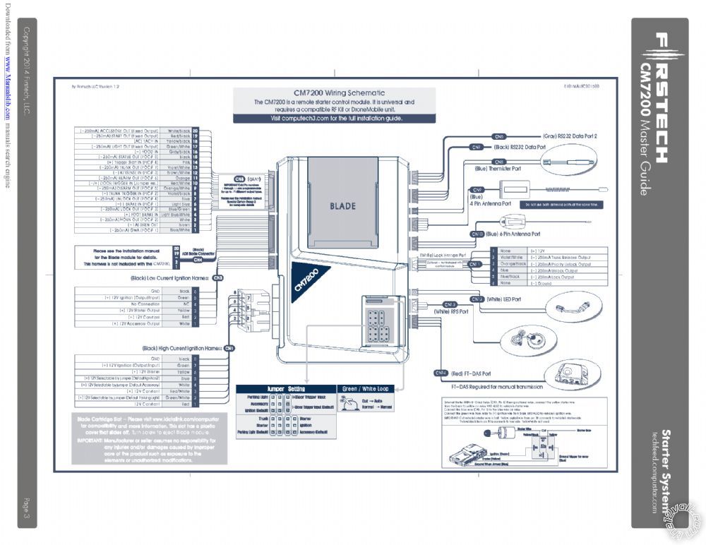
Pretty much all connections. Remember that the install guide wiring guide is primarily focused on the Blade
aspect of the install. It does not show the all of the CM7200s wires. Obvious things like Chassis Ground
is not shown. Other less obvious things like (-) Horn is not shown. In your case you have upgraded the
CN7200s with some alarm functions, so the Siren connection and the DAS are needed. You will have to program
the CM7200 to support the required two Ignition and two Starter outputs.
Just noticed you said manual transmission. The CM7200 would have to be set for Manual Transmission
via the in-cut Green/White loop. Additional wiring would be required to bypass the vehicles clutch
interlock circuit. Unfortunately I have no info on this. Basically, you have to test the switch(es) at the
top of the clutch pedal, find the starter disengage switch, determine how it works and to properly bypass it during
remote start-up. Usually it's by use of a relay controlled by the GWR signal.
The SR Trim level does not have any form of Autolights that I'm aware of. Is the pictured relay still needed?
No. The extra relay is only needed if your truck had an AUTO position on the Headlight Switch.
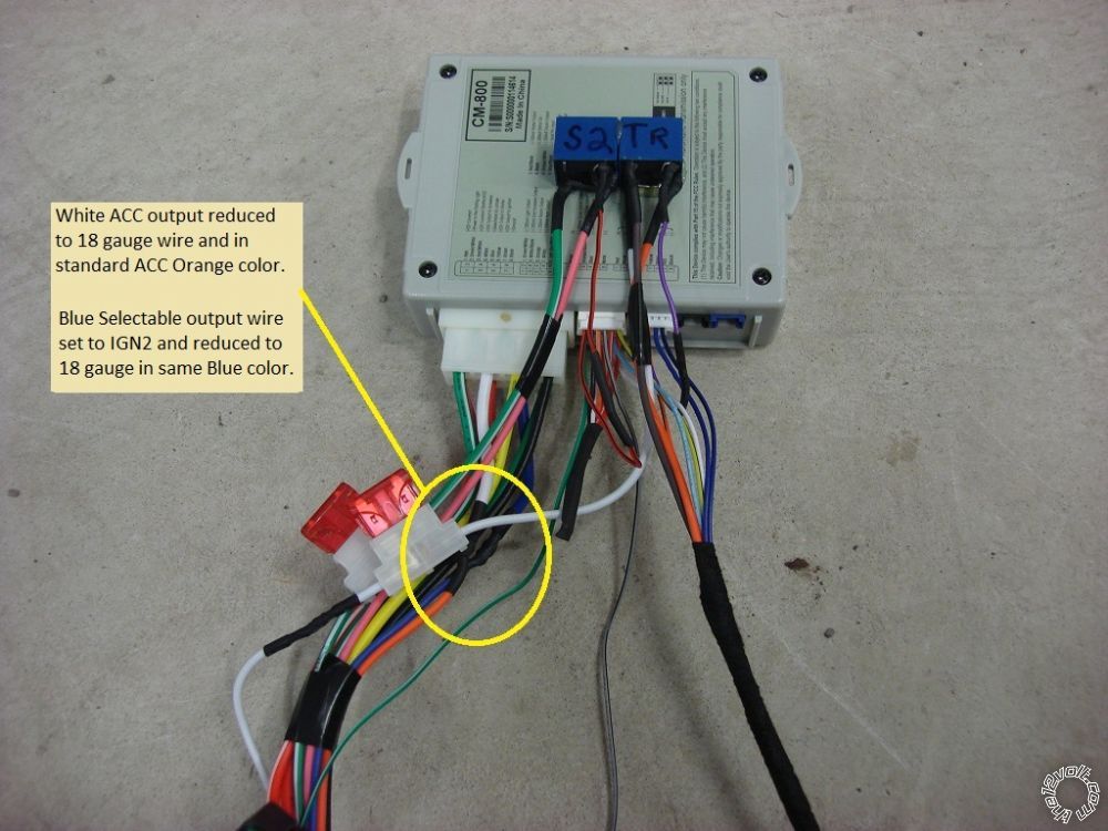
The main Compustar harness is all large gauge, however the ignition switch is a mix of large and smaller gauge wire. Is there an issue connecting say 2nd Ignition Large directly to the smaller OEM wire(after setting proper jumper)?
While it is OK to connect the CN7200's thick ignition type wires directly to the vehicles smaller gauge wires,
I always cut those wires about 3 inches from the CM7200s and solder on quality 18 gauge wires with the same
insulation color. This makes installation and soldering easier. Being as your CM7200 was transferred from
a prior vehicle, it's possible that some of the wires might need to be extended anyway.
What is the best location you would you advise to tap for the 12v input(s)?
While there might be other locations to catch the ignition wires, I usually make those connections at or
very near the ignition switch in the steering column. There is usually enough room in that area to run
the wires. In your case there are only 4 or 5 wires to run and two of those could be 18 gauge if you
reduce the wire gauge of the IGN2 and Starter2 wires like suggested above. I wrap the R/S's wires
that go into the steering column with Tesa tape and ensure there is proper allowances made for the
steering wheels tilt / telescopic movements. Depending on the R/S unit installed and its' features
and power needs, you could run the CM7200's power input wires ( Red and Red/White ) to the thick +12V
constant wire found at the Taco's fuse box instead of the Red wire at Pin 4 of the ignition switch harness.
 Soldering is fun!


-tl9-en_20170929_4.jpg)


 Printable version


