This is a basic Remote Start install Pictorial on a 2004 Jeep Wrangler. This info will be pretty much
the same for the TJ series Wranglers from 1997 through 2004 and the wires necessary for this one button
R/S install.
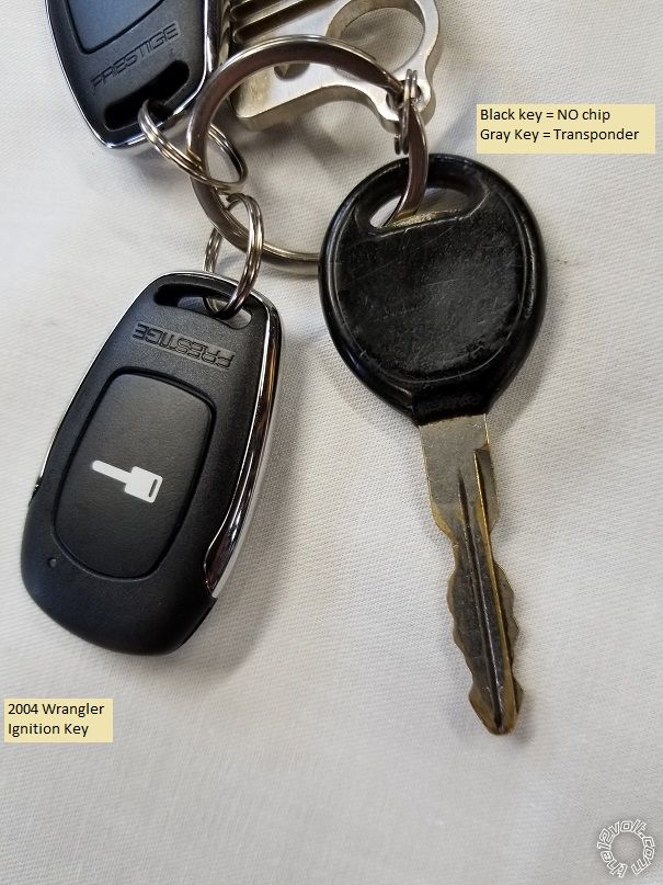
This Jeep had the 4.0 Liter 6 cylinder engine with Automatic transmission. The Jeep did not have power
locks or a Factory Alarm system. The ignition key was one with the Black plastic head and did not have
a transponder chip. Only keys with a Gray head will have a transponder chip.
These Jeeps do not have "one touch starting" or built in Anti-Grind. Running in Tach Mode is a good idea
and adding Anti-Grind is a possible up-sale.
For this vehicle a simple one button APS901E R/S system was used. There are many other quality systems
available. The Black ignition key, no transponder system, made this a low cost install.
Disassembly :
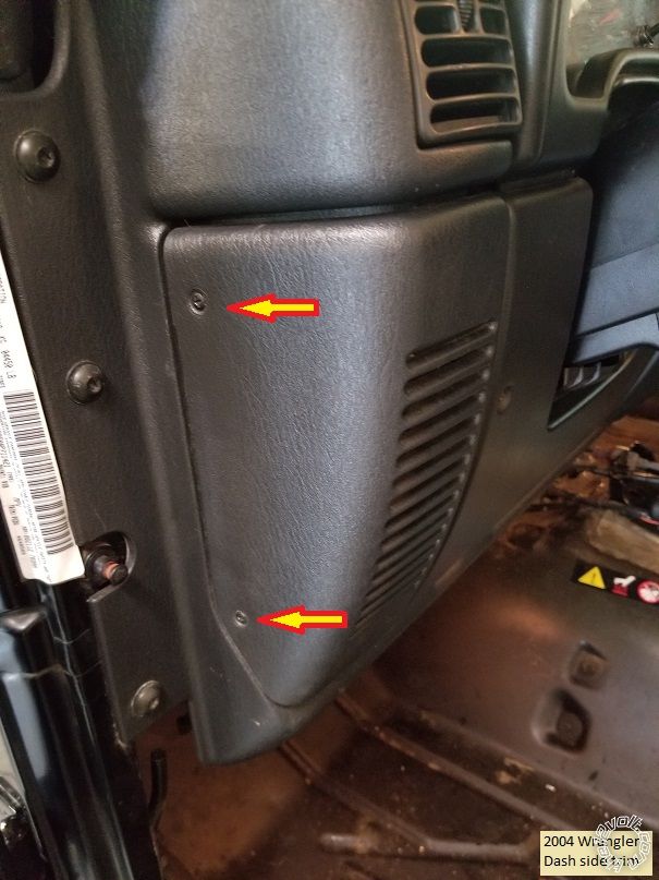
Remove the side dash trim panel by removing the two Phillips screws indicated below and then pull the trim
panel straight back. There are twp clips, top and bottom.
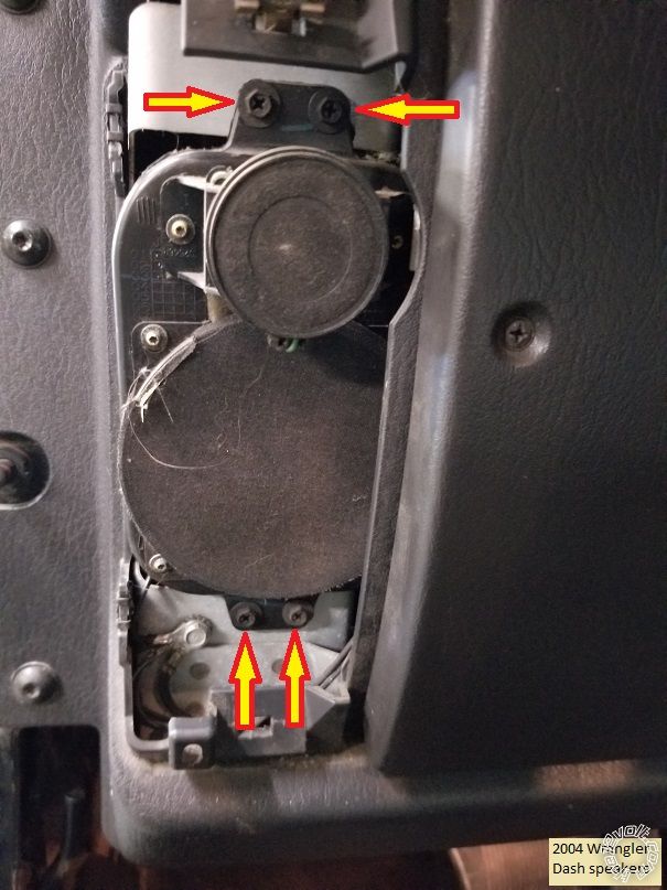
Next remove the four Phillips screws marked below to pull the speakers out of the way to gain access to
the Brake wire and allow easy antenna harness positioning.
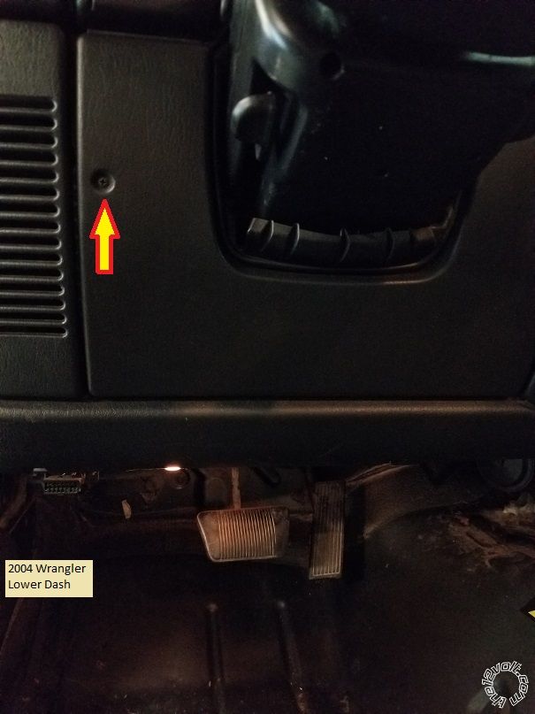
Remove the two Phillips screws ( one on either side of the steering column ) retaining the lower dash panel
and then pull it back and away from the dash.
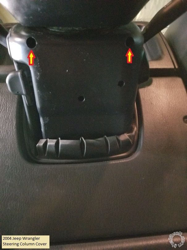
Remove the two Phillips shown at the bottom of the lower steering column cover, then separate the two
cover halves and remove them.
Wires :
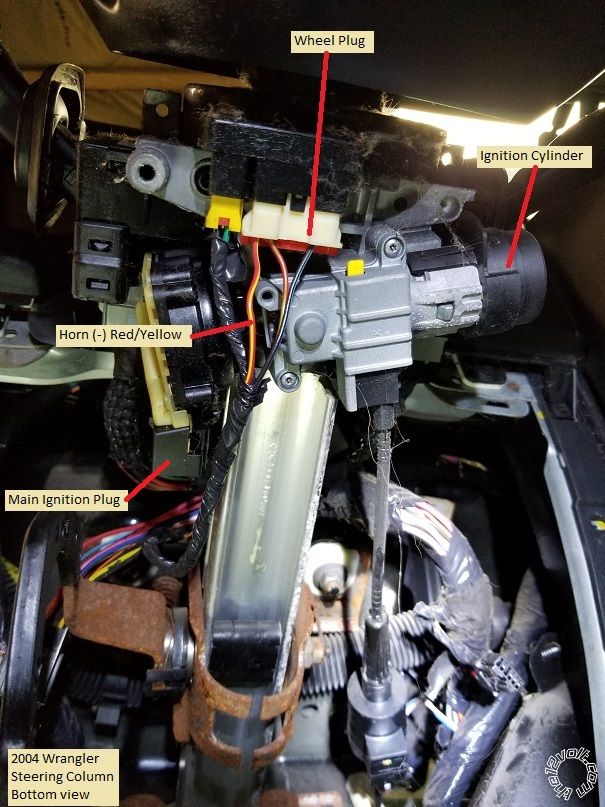
Below is a photo of the left side of the steering column with the important connectors marked.
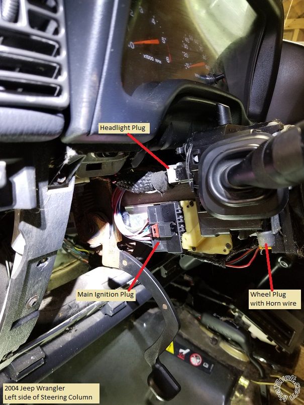
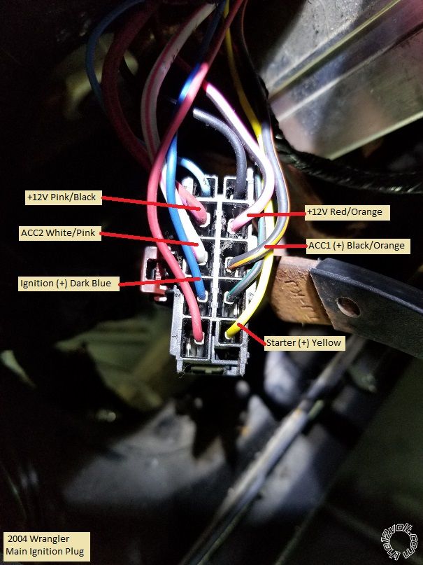
This is a picture of the main ignition connector with the ignition wires indicated.
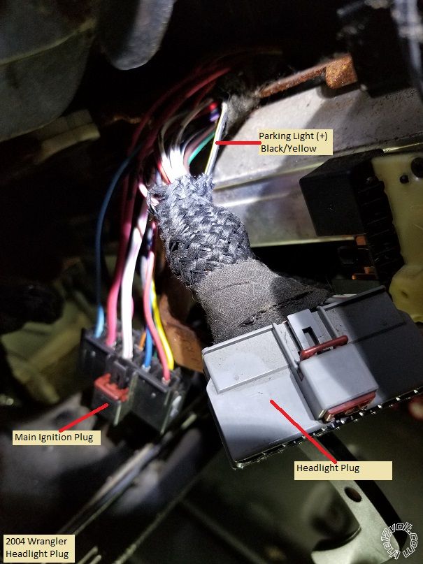
The Parking Light (+) wire is shown in the Headlight connector below.
At the under side of the steering column is the wheel plug with the Horn wire. The APS901E
does not support a horn output but your R/S system might.
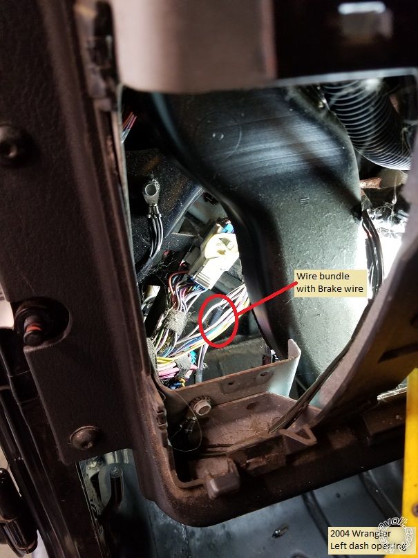
While the Brake wire can be located at the connector at the top of the brake pedal, another location
is in this wire bundle accessed through the dash where the speakers were mounted.
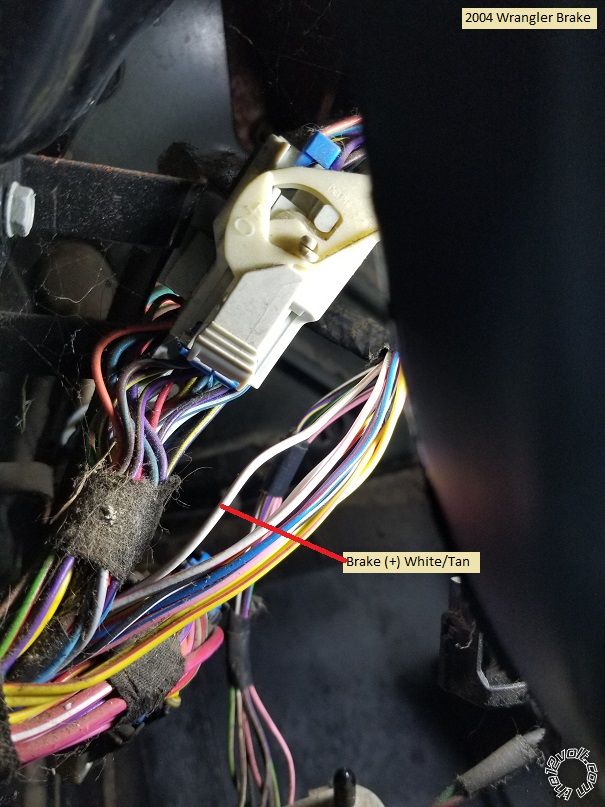
Here is a close up of the Brake wire :
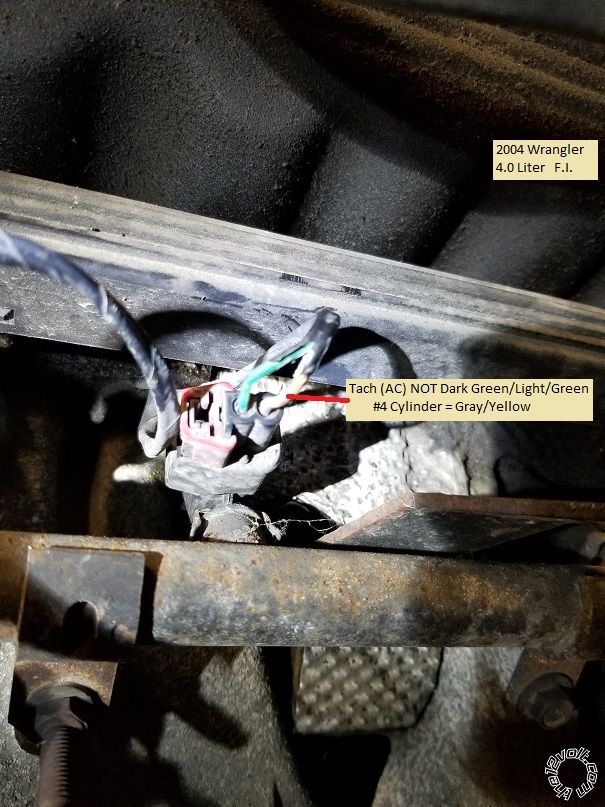
You can obtain a good Tach signal at the PCM ( Blue/Tan wire ) on the passanger side firewall
but another good location is at any F.I. Use the non-common colored wire. On the 4.0 liter engine,
this is any wire NOT Dark Green/Light Green. These are two pin plugs and the wire towards the
firewall is the non-common color Tach signal wire. Photo below :
That is about it. Chassis Ground is available at several locations under the dash. Firewall
pass-through for the Hood Pin and Tach wire is via a firewall grommet. Remember to use a
Digital Multi Meter to locate, test and verify all vehicle wires. Making solder connections
will insure a long lasting install.
Below are the wire connections I used with the APS901E R/S system :
APS-901E...............................................................to 2004 Jeep Wrangler
6 Pin Power
1. Blue..................Ignition................................Dark Blue at ignition switch harness
2. Red/White ......+12V Constant....................Pink/Black at ignition switch harness
3. Green................Ignition2/Accessory2.........White/Pink at ignition switch harness
4. Purple................Accessory..........................Black/Orange at ignition switch harness
5. Red....................+12V Constant..................Red/Orange at ignition switch harness
6. Yellow..................Starter...............................Yellow at ignition switch harness
12 Pin Harness
1. Gray/Black............ Hood Pin (-).......................Mercury Switch on hood hinge
2. Gray.........................(-) Inhibit...........................not used
3. Light Blue................GWR................................not used
4. Brown......................(+) Inhibit..........................not used
5. Black/Lt Green.......Pulse After Shutdown.......not used
6. Brown/Black...........Brake Shutdown (+)..........White/Tan in wire bundle
7. Black/Blue..............Pulse Before Start.............not used
8. Green......................Unlock................................not used
9. Black/Red...............Pulse After Shutdown........not used
10. Green/Yellow..........Wait to Start / GlowPlug...not used
11. Black/Yellow...........Pulse During Crank..........not used
12. Green/Orange........Tach...................................F.I. non-common color wire
White 4 Pin
1. White..................Parking Light Out..................Black/Yellow at Headlight Switch
2. White/Red..........Parking Light In.....................Red at APS901E 6 Pin +12V input
3. Yellow/Black........Controlling Alarm IGN..........not used
4. Black...................Chassis Ground....................Chassis Ground
Soldering is fun!


 Printable version


