the12volt.com spacer
icon

Adding Third Ignition to Viper Remote Start for 2007 BMW X3


Post ReplyPost New Topic
< Prev Topic Next Topic >
chem.eng 
Member - Posts: 10
Member spacespace
Joined: August 20, 2017
Posted: September 15, 2019 at 12:59 AM / IP Logged Link to Post Post Reply Quote chem.eng
I am currently installing a Viper 4706V into my 2007 BMW X3 (USA). I am trying to prep and make it ready for installation into my vehicle. The issue I am having is making sure I properly wire the ignition wires correctly.
According to the DirectWire for 2007 BMW X3:
Ignition 1 is a green wire
Ignition 2 is a purple wire
Ignition 3 is a red/black or red/blue wire
Since the Viper 4706V only has two ignition wires:
Ignition 1 - Pink Wire
Ignition 2 - Pink/White Wire
The issue is there is no third ignition wire on the 4706V, I will need to use Ignition 2 on the remote start to trigger two relays to supply voltage to Ignition 2 and 3 on the the car. This I understand and if there is a better way please let me know. My struggle is the note that DirectWire left for second ignition, "This wire needs to be powered before ignition. Use status or ground when running to trigger." This statement confused me so I checked another website and they said for the second ignition, "This wire must power up before Ignition 1, use the (-) Ignition 3 output." Still this did not help me to understand this anymore.
Can someone please explain this to me and share their experience installing into a BMW X3? I appreciate any help and hope this might help someone later too.
kreg357 
Platinum - Posts: 7,783
Platinum spaceThis member has made a donation to the12volt.com. Click here for more info.spaceThis member has been recognized as an authority in Electrical Theory. Click here for more info.spaceThis member has been recognized as an authority in Mobile Security and Convenience. Click here for more info.spacespace
Joined: January 30, 2009
Location: Pennsylvania, United States
Posted: September 15, 2019 at 4:53 PM / IP Logged Link to Post Post Reply Quote kreg357
I've never done an X3 but if your info in correct, here is how to do it.
Viper ING1 to X3 Green
Viper IGN2 to X3 Red/Black or Red/Blue
For the X3's IGN2 wire, you will need one 30/40 Amp SPDT relay. Here is the wiring :
Relay Pin 86 and 87 to +12V constant ( fuse appropriately )
Relay Pin 30 to X3 ING2 Purple
Relay Pin 85 to Viper Blue/White ( 2nd Status / Rear Defrost )
Relay Pin 87A not used
Using the 2nd Status signal to control the 2nd Ignition Relay will get it to power
up the X3's 2nd Ignition wire before the Viper brings up the other thick IGN1 and IGN2
wires. This lead time is around 1 second if memory serves me depending on the R/S
manufacturer.
I'm assuming that you will use the Viper Blue Status wire for your bypass module
and that you are not planning on using the Viper Blue/White for Defrost.
Soldering is fun!
chem.eng 
Member - Posts: 10
Member spacespace
Joined: August 20, 2017
Posted: September 18, 2019 at 2:08 AM / IP Logged Link to Post Post Reply Quote chem.eng
Thank You kreg357, I appreciate the help. I was looking at the wiring diagram for the BMW X3 ignition and I was wondering if you could give me your opinion/advice?
Below is the image of the wiring diagram, on top are three voltage sources going down into the ignition switch and then below are the starter and three ignition wires.
Adding Third Ignition to Viper Remote Start for 2007 BMW X3 -- posted image.
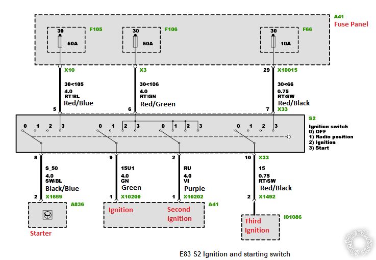
I was considering for the fused (+)12V constant input of the remote start flex relay if I should use Pin 7 the red/black wire (top right wire) to power the third ignition wire (Pin 10 - Red/Black). The DirectWire does not reference this wire and never mentions it. I need to supply the Ignition #2 fused 12V input power on the remote start, the only sources DirectWire recommends or lists are Pin 5 (red/blue) and Pin 6 (red/green) wires which are 50 amp circuits. The reason I ask is the third ignition wire on the ignition switch appears to make contact to a 10 amp circuit from Pin 7 (red/black) wire.
This may be excessive and unnecessary since a fuse is used anyways but it keeps the circuits separated and I thought I would ask for other opinions.
Would you power the starter and three ignition wires with the two 50 amp 12 volt sources or use the 10 amp circuit (Pin 7 - red/black) to power the third ignition wire of the vehicle?
kreg357 
Platinum - Posts: 7,783
Platinum spaceThis member has made a donation to the12volt.com. Click here for more info.spaceThis member has been recognized as an authority in Electrical Theory. Click here for more info.spaceThis member has been recognized as an authority in Mobile Security and Convenience. Click here for more info.spacespace
Joined: January 30, 2009
Location: Pennsylvania, United States
Posted: September 18, 2019 at 6:34 PM / IP Logged Link to Post Post Reply Quote kreg357
I think I would handle the Viper's ignition wire +12V supply this way.
Viper Red and external IGN2 relay go to the X3's Red/Green 50 Amp wire.
Viper Red/Black wire goes to the X3's Red/Blue 50 Amp wire.
Viper Red/White wire goes to the X3's Red/Black 10 Amp wire.
Logoc :
The Viper's Red wire supplies power to IGN1 Pink output wire.
The Viper's Red/Black wire supplies power to the Starter ( Purple ) and Accessory ( Orange ) output wires.
The Viper Red/White wire supplies power to the White IGN2 wire.
The X3's 50 Amp Red/Green wire supplies power to the X3's IGN1 and IGN2 circuits so connecting the Vipers Red and the external relay's power input won't overload it.
The X3's IGN3 circuit only needs 10 Amps so it can supply the Vipers IGN2 White IGN2 wire properly.
Soldering is fun!
catback 
Silver - Posts: 703
Silver spacespace
Joined: August 13, 2002
Location: Canada
Posted: September 22, 2019 at 9:50 AM / IP Logged Link to Post Post Reply Quote catback
From the diagram, the "Third Ignition" looks like a second starter - it's only HOT when the key in the start position.
chem.eng 
Member - Posts: 10
Member spacespace
Joined: August 20, 2017
Posted: September 29, 2019 at 9:30 PM / IP Logged Link to Post Post Reply Quote chem.eng
Thank you both kreg357 and catback.
Kreg357 I have another question for you. I started to wire up the R/S module and noticed the third ignition wire of the X3 only powers the heated steering wheel. Most importantly it can not be triggered to turn on unless I physically hit the button to power it on. The switch only has a power and a ground wire going to it. I see no reason to connect this wire.
So my question to you is can I use the R/S flex relay ignition 2 (pink/white wire) to power the X3 ignition 2 (purple wire) and make the flex relay ignition 2 (pink/white wire) trigger before ignition 1 (pink) of the R/S as required by DirectWire?
Is there a way to wire it this way or do I still need to use an external relay and wire it the way we discussed with the blue/white status wire of the R/S?
kreg357 
Platinum - Posts: 7,783
Platinum spaceThis member has made a donation to the12volt.com. Click here for more info.spaceThis member has been recognized as an authority in Electrical Theory. Click here for more info.spaceThis member has been recognized as an authority in Mobile Security and Convenience. Click here for more info.spacespace
Joined: January 30, 2009
Location: Pennsylvania, United States
Posted: October 03, 2019 at 9:59 AM / IP Logged Link to Post Post Reply Quote kreg357
I am not aware of any way to change the "turn on" timing for the Pink/White ING2 wire.
Pretty sure Viper has it set up to be exactly the same as Pink IGN1.
Using (-) Status Output or 2nd Status with a relay will provide the early signal needed.
Soldering is fun!

If you wish to post a reply to this topic, you must first login.
If you are not already registered, you must first register.

  Printable version Printable version Post ReplyPost New Topic
You cannot post new topics in this forum
You cannot reply to topics in this forum
You cannot delete your posts in this forum
You cannot edit your posts in this forum
You cannot create polls in this forum
You cannot vote in polls in this forum

  •  
Search the12volt.com
Follow the12volt.com Follow the12volt.com on Facebook
Friday, April 26, 2024 • Copyright © 1999-2024 the12volt.com, All Rights Reserved Privacy Policy & Use of Cookies
Disclaimer: *All information on this site ( the12volt.com ) is provided "as is" without any warranty of any kind, either expressed or implied, including but not limited to fitness for a particular use. Any user assumes the entire risk as to the accuracy and use of this information. Please verify all wire colors and diagrams before applying any information.

Secured by Sectigo
the12volt.com spacer
Support the12volt.com
Top
the12volt.com spacer