Well, there's some good news and some bad news. The good news is the car is OK. The bad news is the Viper has an issue. Verify that the Parking Light jumper is still in place and on the correct (+) or (-) setting for your car. Not sure what changed but you should verify all your Viper connections. It might even be a good idea to list all the connections. Here is a harness pin listing to assist :
Main (Primary) Harness, White 12-pin connector
1 ORANGE (-) 500mA GWA (Ground When Armed) OUTPUT
2 WHITE (+/-) SELECTABLE PARKING LIGHT OUTPUT
3 WHITE/BLUE (-) 200mA CHANNEL 3 PROGRAMMABLE OUTPUT
4 BLACK/WHITE (-) 200mA DOMELIGHT SUPERVISION OUTPUT
5 GREEN (-) DOOR TRIGGER INPUT, ZONE 3
6 BLUE (-) INSTANT TRIGGER INPUT, ZONE 1
7 VIOLET (+) DOOR TRIGGER INPUT, ZONE 3
8 BLACK (-) CHASSIS GROUND INPUT
9 YELLOW (+) SWITCHED IGNITION INPUT, ZONE 5
10 BROWN (+) SIREN OUTPUT
11 RED (+) CONSTANT POWER INPUT
12 RED/WHITE (-) 200mA CHANNEL 2 OUTPUT
Door Lock Harness, 3-pin connector
1 LIGHT BLUE 200 mA (-) UNLOCK, 200 mA (+) LOCK OUTPUT
2 EMPTY NOT USED
3 GREEN 200 mA (-) LOCK, 200 mA (+) UNLOCK OUTPUT
I would disconnect the White Parking Light wire and see if the Viper works without it, siren chirps, etc.
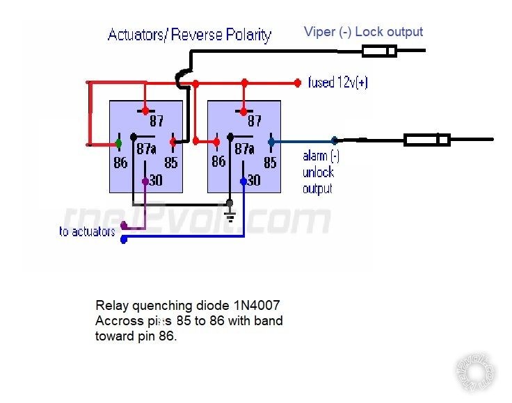
Your relay wiring was probably correct beinmg as you have 2 wire solenoids that are not used or connected to anything else, only the Viper. Below is a link to the correct relay wiring diagram for your Type D setup.
Actuators / Reverse Polarity Relay Diagram (Type D) https://www.the12volt.com/doorlocks/multiple-wire-car-door-locks.asp#arp
As a test, you could wire up the relays as per the diagram but don't connect the Vipers lock outputs. You can test the operation by briefly touching a jumper wire that goes to chassis ground to the relays alarm input pins. That will simulate the Vipers one second lock or unlock output and make the solenoid change position. If that works OK you can connect the Vipers lock outputs to the proper relay. If your 3105V Viper system has the old style (+) / (-) outputs, I would place a 1N4001 diode in that output wire with the diodes band towards to Viper. This will block the unused/unwanted (+) output. Additionally, I would put a 1N4004 or 1N4007 diode across the relays coil ( Pin 85 - Pin 86 ). Please note that the diagram does not follow standard relay conventions. Pin 85 should receive the (-) signal and Pin 86 should get the (+) signal. The diagram will work, but... The diagram shows the relay on the left with those input polarities reversed, probably to make the diagram easier. Below is the corrected diagram.
 Soldering is fun!


 Printable version


