the12volt.com spacer
icon

2001 Mazda 323 or Protegé or Familia BJ Chassis Non-US


Post ReplyPost New Topic
< Prev Topic Next Topic >
12vdoog 
Member - Posts: 4
Member spacespace
Joined: August 09, 2020
Location: Indiana, Argentina
Posted: August 09, 2020 at 4:51 PM / IP Logged Link to Post Post Reply Quote 12vdoog
Hi, indeed there are several topics already with the damn 323 or Protegé (depending on which country are you).
Straight to the point, I don't have a fancy alarm, is one of those 2001 Mazda 323 or Protegé or Familia BJ Chassis Non-US -- posted image. chinese ones. I bought it in a hurry since I just bought the car and it did not have any kind of protection system besides the door locking system.
Now, I did mess up before even finding you guys, because I had the service manual of the car and the wiring diagram, spent 2 days planning and supposedly all was going to be easy... for a 6ft tall person is not easy to install an alarm, specially in tight spaces.
Anyways, so, what I had thought was to tap to the door actuator from the door control system and that would be it... WRONG. As many times I had read now, this is a one wire system, the thing is, which is the wire and how do I wire it?
2001 Mazda 323 or Protegé or Familia BJ Chassis Non-US -- posted image.
As you can see, this model does not seem to be completely the same as the US model.
Next, is what I had in mind, but is it WRONG, using creates some short and the wires start to get hot also.
2001 Mazda 323 or Protegé or Familia BJ Chassis Non-US -- posted image.
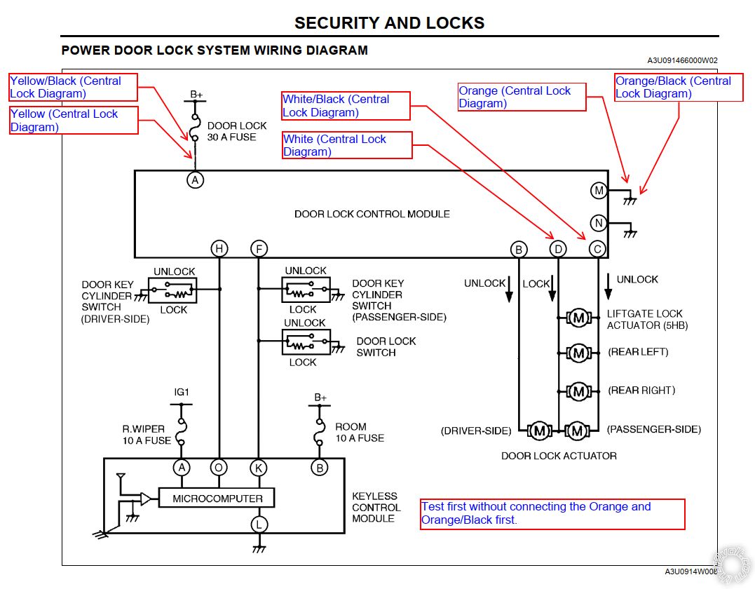
The thing is that, the diagram above, does not match the non-US model, since I'm missing pins: B, H, I, J. I know some are not there because I do not have the factory alarm.
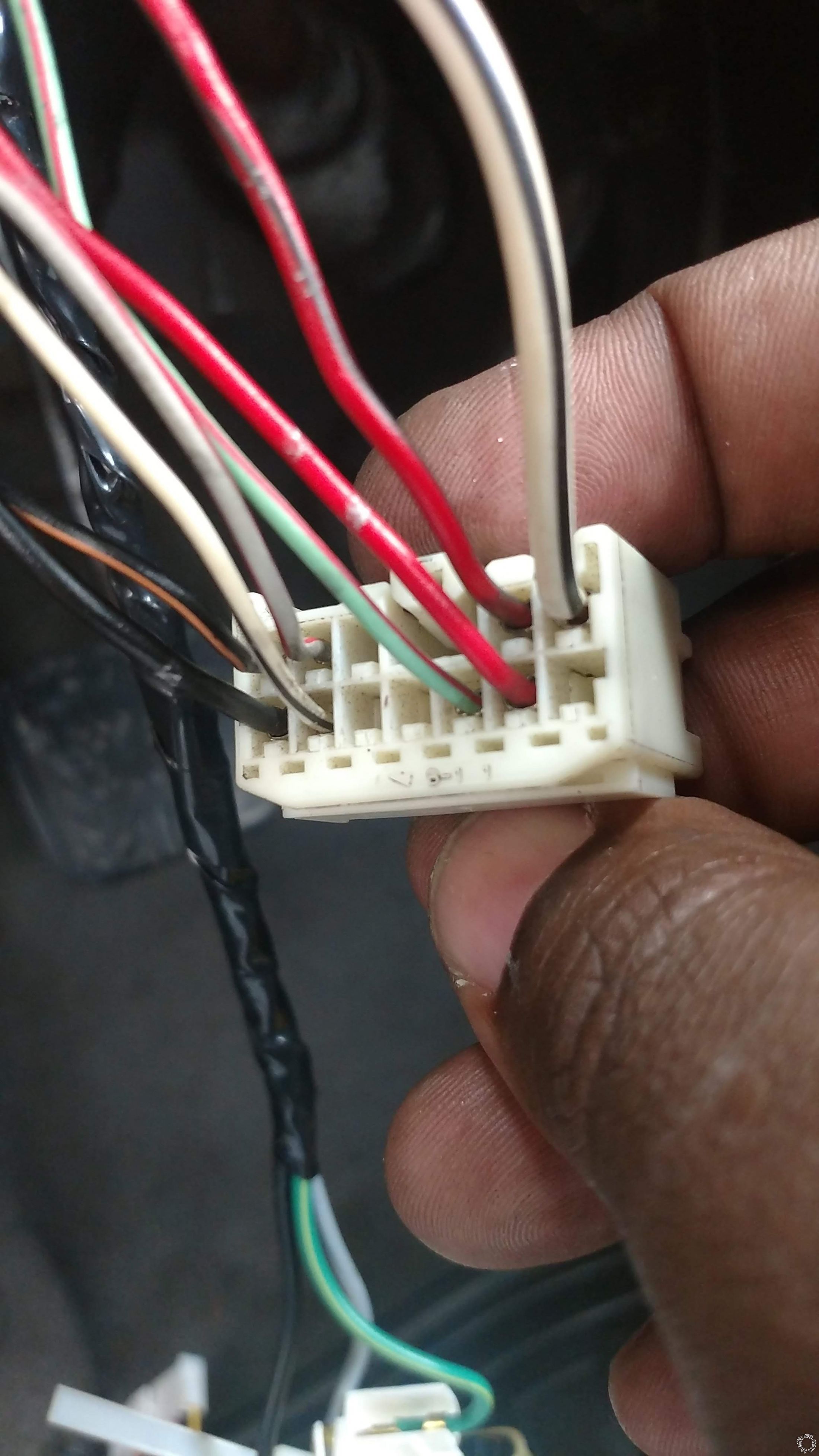
The problem so far for the door locking, pin K show 5V when locked and 0V when open, and pin L show 5V when open and 0V when closed.. Those pins appear as empty on the wiring diagram in the service manual.
Pin F does not show anything, I mean literally no voltage or something like 0.1 when actuating the driver side door lock, so I do not know how to interpret this. Is this the ONE-WIRE that I'm supposed to tag into? could it be pin F (green/red wire?)
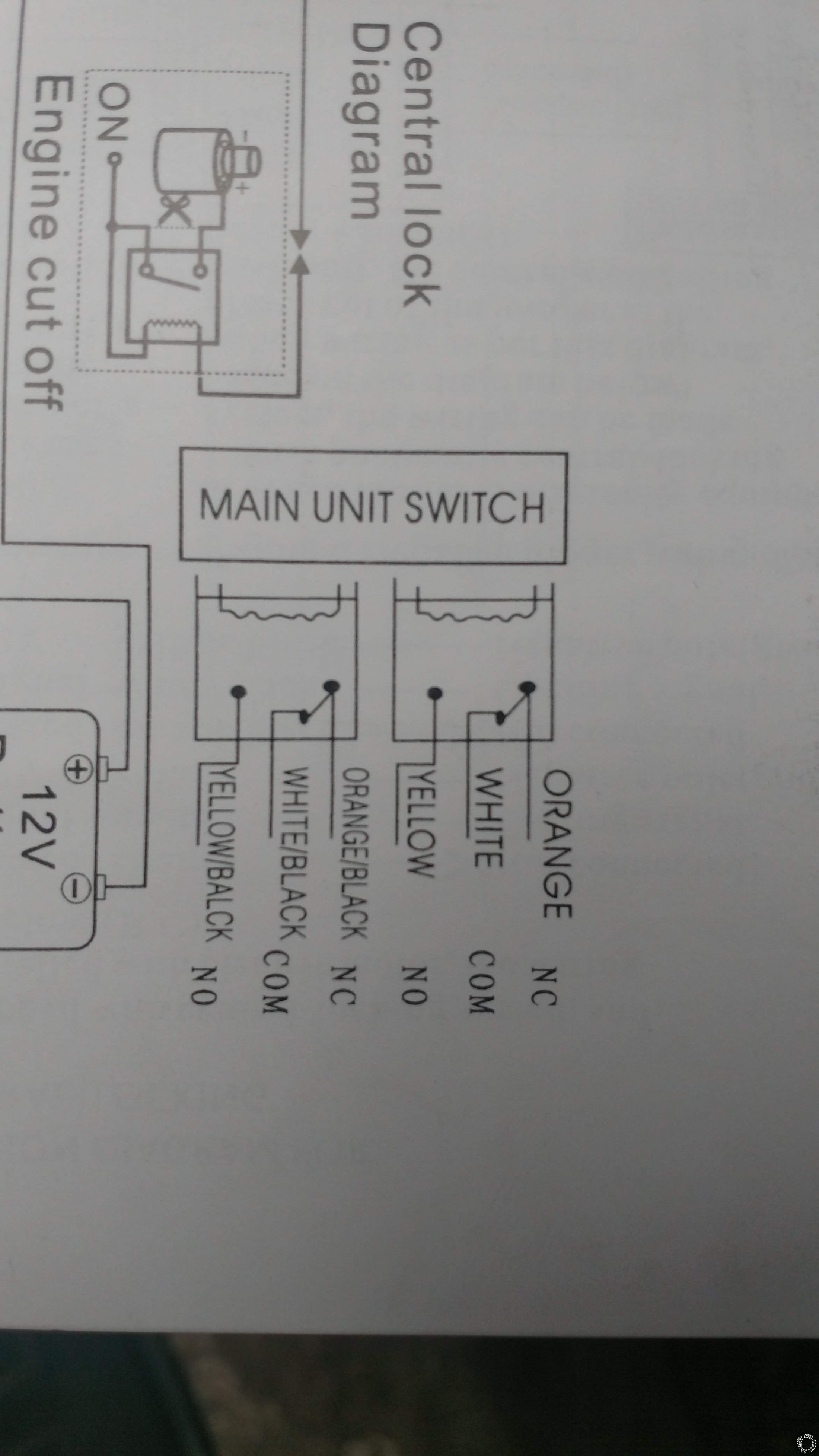
Moving forward, this is the diagram that I have from the alarm that I bought, again, sorry indeed, just a cheap china made, I promise to change it for a better brand name next year.
2001 Mazda 323 or Protegé or Familia BJ Chassis Non-US -- posted image.
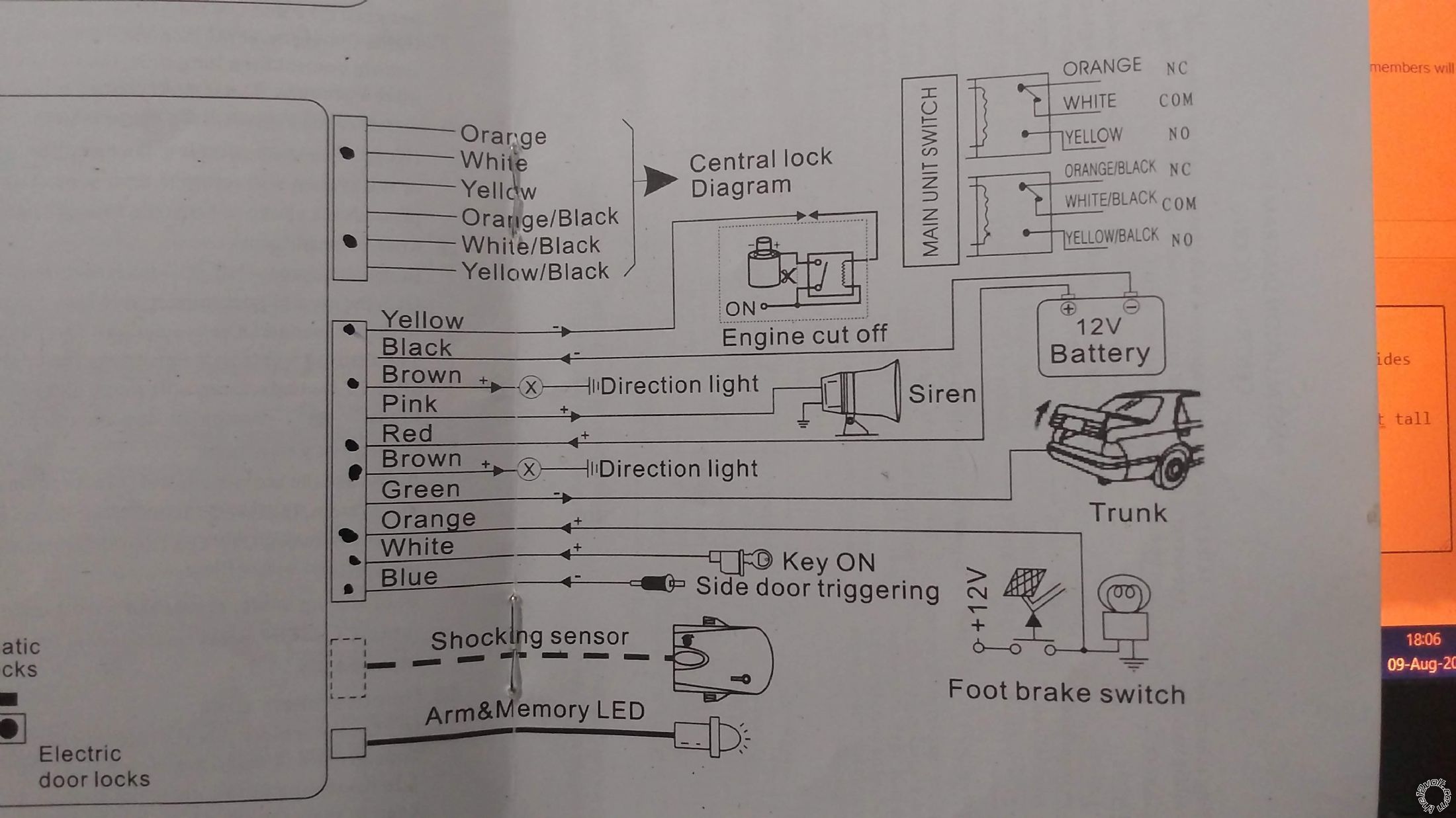
And a close up of the wiring of the door locking from the alarm side:
2001 Mazda 323 or Protegé or Familia BJ Chassis Non-US -- posted image.
Now, I see that you guys mentioned an 1500 ohm resistor, the next question is: which wire is the trigger of the door? and how do I solder this resistor to the signals of the alarm?
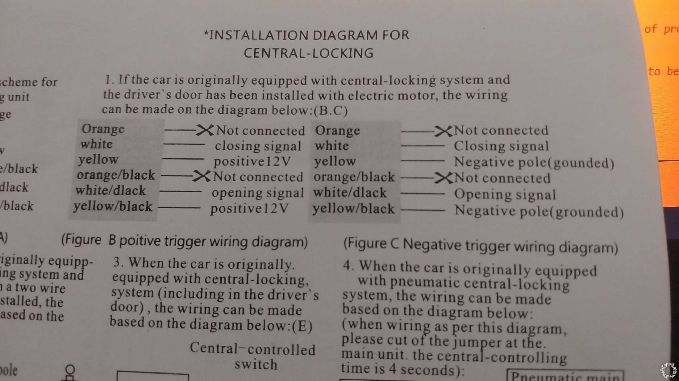
I also see this diagram: JBS alarm diagram one wire system
And this one: Bulldog diagrams
I going to suppose that for the closing signal (white wire on the alarm) goes to the one-wire WITH resistor and the opening signal (white black wire on the alarm) goes WITHOUT resistor to the one-wire. The question is, where is this one-wire? could it be that one that showed 0.1v?
So far I have wired most of the stuff of the alarm, and so far I have to wire the door locking, the door trigger (which I know is a black blue wire but... I need to disassemble more since I do not fit quite in there... you know... 6ft tall here.
kreg357 
Platinum - Posts: 7,783
Platinum spaceThis member has made a donation to the12volt.com. Click here for more info.spaceThis member has been recognized as an authority in Electrical Theory. Click here for more info.spaceThis member has been recognized as an authority in Mobile Security and Convenience. Click here for more info.spacespace
Joined: January 30, 2009
Location: Pennsylvania, United States
Posted: August 09, 2020 at 5:18 PM / IP Logged Link to Post Post Reply Quote kreg357
Here is a link to Directed TechTip 1041 :   https://www.the12volt.com/installbay/file.asp?ID=1213
It has very good with info on the various door lock systems. From you wiring info, it looks like a Type H system. The TechTip describes how to determine the correct resistor value. The only hard part will be setting up the wiring for your system and it's internal relays. The vehicle connection point could be on the wire between F and K if you wanted a single pulse to unlock all doors at once. Use the wire between points H and O if you want Progressive Unlock ( first unlock pulse unlocks the drivers door, second unlock unlocks the rest of the doors.
Soldering is fun!
12vdoog 
Member - Posts: 4
Member spacespace
Joined: August 09, 2020
Location: Indiana, Argentina
Posted: August 09, 2020 at 5:49 PM / IP Logged Link to Post Post Reply Quote 12vdoog
Forgot to mention I do not have the keyless entry system, but after seeing the tech tip 1041, now I understand, and after matching the info with the service manual, now I understand the resistor thing, I need the resistor to lock and no resistor to unlock, on the F pin.
Now, the K and L pins, since there show 5V, I assume there is a BCM, so I won't mess with them, do not want to burn any computer thingy.
Tomorrow I will get the resistor and try.
Then... to disassemble the kick side panel and search for the door trigger.
Thanks for the info.
i am an idiot 
Platinum - Posts: 13,667
Platinum spaceThis member consistently provides reliable informationspace
Joined: September 21, 2006
Location: Louisiana, United States
Posted: August 09, 2020 at 6:26 PM / IP Logged Link to Post Post Reply Quote i am an idiot
Power Lock      lt green/red      - 1500 ohms      module high in driver kick           
Power Unlock      same wire      -           
12vdoog 
Member - Posts: 4
Member spacespace
Joined: August 09, 2020
Location: Indiana, Argentina
Posted: August 13, 2020 at 4:35 PM / IP Logged Link to Post Post Reply Quote 12vdoog
Guys... guess what?
the damn green/red... seems to be not connected to the door system. I took the green/red out of the connector (it has a nice tab system to take the wires out without cutting) and actuated the door lock and all door opened and closed WITHOUT the green/red connected to the module.
Now check this out:
When I open the door lock:
Gray/Red has 5V
White/Black has 0V
When I close the door lock:
Gray/Red has 0V
White/Black has 5V
So... that means that the wiring is not quite, standard as the model I have is non-us.
Since those two have 5V, that means that they go to the ECM or the Door Lock relay has some 5V circuitry...
Help please 2001 Mazda 323 or Protegé or Familia BJ Chassis Non-US -- posted image. 2001 Mazda 323 or Protegé or Familia BJ Chassis Non-US -- posted image. 2001 Mazda 323 or Protegé or Familia BJ Chassis Non-US -- posted image. 2001 Mazda 323 or Protegé or Familia BJ Chassis Non-US -- posted image. 2001 Mazda 323 or Protegé or Familia BJ Chassis Non-US -- posted image.
12vdoog 
Member - Posts: 4
Member spacespace
Joined: August 09, 2020
Location: Indiana, Argentina
Posted: August 14, 2020 at 5:46 PM / IP Logged Link to Post Post Reply Quote 12vdoog
So, finally I installed the car alarm minus the door locking system.
Why?: the driver's door DOES NOT have the oem actuator or any actuator, what it seems to have is a dummy actuator that signals the 5V to the door locking module:
Quote:
When I open the door lock:
Gray/Red has 5V
White/Black has 0V
When I close the door lock:
Gray/Red has 0V
White/Black has 5V
Now, since this models is non-us, DOES NOT have keyless entry, DOES NOT have the actuator on the driver's door, using the wiring diagram of the site helps only to install the alarm minus the door system.
BUT, using my diagram WHILE DISCONNECTING AND REMOVING the door locking module AND ADDING an actuator for the driver's door, gives you the full alarm with the door locking controlled by the alarm.
I'm satisfied, since the alarm is installed at least, partially, but it is.
One note: the wiring to the doors DOES HAVE the wires for the actuators on all the doors, so you can install some generic or non-oem ones, but I will do that by the end of the year... if I survive this pandemic too :P
Thanks for the guidance guys.

If you wish to post a reply to this topic, you must first login.
If you are not already registered, you must first register.

  Printable version Printable version Post ReplyPost New Topic
You cannot post new topics in this forum
You cannot reply to topics in this forum
You cannot delete your posts in this forum
You cannot edit your posts in this forum
You cannot create polls in this forum
You cannot vote in polls in this forum

  •  
Search the12volt.com
Follow the12volt.com Follow the12volt.com on Facebook
Wednesday, April 24, 2024 • Copyright © 1999-2024 the12volt.com, All Rights Reserved Privacy Policy & Use of Cookies
Disclaimer: *All information on this site ( the12volt.com ) is provided "as is" without any warranty of any kind, either expressed or implied, including but not limited to fitness for a particular use. Any user assumes the entire risk as to the accuracy and use of this information. Please verify all wire colors and diagrams before applying any information.

Secured by Sectigo
the12volt.com spacer
Support the12volt.com
Top
the12volt.com spacer