the12volt.com spacer
icon

Viper 5806V, 1964 Chevrolet Impala


Post ReplyPost New Topic
< Prev Topic Next Topic >
lchingon 
Member - Posts: 5
Member spacespace
Joined: February 04, 2020
Location: Idaho, United States
Posted: December 29, 2020 at 7:35 PM / IP Logged Link to Post Post Reply Quote lchingon
Any help would be appreciated. Installed a 5806V alarm in a 1964 impala. Installed 2 wire DEI 524N Hi power door lock motors using DEI 451M DOOR LOCK MODULE RELAY. Very simple install, took green/blue connector that came with the 5806 alarm, plugged it into the brain, then wired 451M relay (white/black+brown/black=ground, violet+violet/black=12v, green to one side of actuator and blue to other side of actuator, took small green/blue wires and connected them to 5806v module green/blue wires). I get no lock/unlock function when arming/disarming the alarm. I searched the alarm manual to see if there was a setting I was missing but could not find one. If I take the green/blue plug off the alarm module and put a +12/ground on the wires (the wires that go to the 451M relays) I can get the relay to actuate thus actuating the door lock actuator so it is definitely missing the output signal from the alarm module, although the door lock actuators don't seem to have a lot of push/pull on them like the power is weak. i double checked all my connections (soldered most of them) and definitely have good 12v and ground to the relays. thanks! eddie
lchingon
Ween 
Platinum - Posts: 1,364
Platinum spacespace
Joined: August 01, 2004
Location: Illinois, United States
Posted: December 29, 2020 at 9:55 PM / IP Logged Link to Post Post Reply Quote Ween
Does the pigtail on the 451M that plugs into the 5806 have 2 or 3 wires.   Connect thin red to battery power (purple, purple/black), the relay coils need a power source. The 5806 is supplying the ground to activate the relay coils.
lchingon 
Member - Posts: 5
Member spacespace
Joined: February 04, 2020
Location: Idaho, United States
Posted: December 29, 2020 at 10:52 PM / IP Logged Link to Post Post Reply Quote lchingon
I figured it out. the 5806V manual states the center red wire on the door lock/unlock harness is not used and basically serves no purpose. The 451M manual in a short sentence says this wire provides 12v to the relay, but the other 2 voilet/violet+black also provide power to the relay. Based on all this and the way 2 relays are wired I figured the red wire was not needed so I cut it. Once I spliced it back up and used one of the 451M harnesses to plug into the 5806V module the lock actuators started to work. i wish there were better schematics of the 451M, I would have saved myself 2 hours of troubleshooting. LOL.
lchingon
lchingon 
Member - Posts: 5
Member spacespace
Joined: February 04, 2020
Location: Idaho, United States
Posted: December 30, 2020 at 1:30 PM / IP Logged Link to Post Post Reply Quote lchingon
thanks for the help man!
lchingon
lchingon 
Member - Posts: 5
Member spacespace
Joined: February 04, 2020
Location: Idaho, United States
Posted: January 09, 2021 at 2:45 PM / IP Logged Link to Post Post Reply Quote lchingon
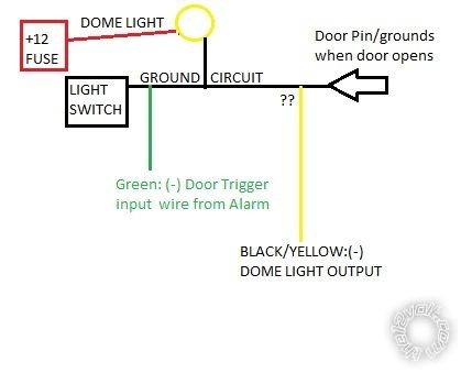
thanks up front for the help! Installing a VIPER 5806v alarm in a 1964 Chevy Impala with Door pins that "ground" when the door is opened. I have it all connected except the BLACK/YELLOW:(-) DOME LIGHT OUTPUT and it all works fine. My questions is if I can connect this BLACK/YELLOW dome wire to the same location the Green (-) DOOR TRIGGER INPUT wire is connected? I don't want to blow either circuit. I assume the DOME LIGHT OUTPUT is a NEGATIVE/GROUND that only activates when the alarm is turned OFF, "this output activates when disarming /unlocking the system and when turning the ignition off in the vehicle". I am assuming that the green wire is detecting a ground when the alarm is ON and thus the DOME LIGHT circuit would be OFF during this time. When the alarm is turned OFF the alarm turns "off" the sensing for the GREEN wire and activates the GROUND for the dome light, basically always opposite of each other. Seems simplistic but again, I don't want to fry my module. I included the a wiring diagram based on the cars wiring schematic. thanks again for the help!
Viper 5806V, 1964 Chevrolet Impala - Last Post -- posted image.
lchingon
Ween 
Platinum - Posts: 1,364
Platinum spacespace
Joined: August 01, 2004
Location: Illinois, United States
Posted: January 09, 2021 at 6:21 PM / IP Logged Link to Post Post Reply Quote Ween
Page 9 of the installation manual gives description of the dome light output. It is a negative output, but is limited to 200mA.   200mA is less than most incandescent bulbs, so the output would need to trigger a relay. The relay contacts would then supply a negative output to the domelight circuit. Don't forget that the car may also have courtesy lights in parallel with the dome light.
lchingon 
Member - Posts: 5
Member spacespace
Joined: February 04, 2020
Location: Idaho, United States
Posted: January 09, 2021 at 10:35 PM / IP Logged Link to Post Post Reply Quote lchingon
Thanks for the reply and info. based on your feedback just add a relay to supply a negative output to the circuit. So the dome/door pin can both connect together at the same point without hurting either circuit. thanks again!
lchingon

If you wish to post a reply to this topic, you must first login.
If you are not already registered, you must first register.

  Printable version Printable version Post ReplyPost New Topic
You cannot post new topics in this forum
You cannot reply to topics in this forum
You cannot delete your posts in this forum
You cannot edit your posts in this forum
You cannot create polls in this forum
You cannot vote in polls in this forum

  •  
Search the12volt.com
Follow the12volt.com Follow the12volt.com on Facebook
Friday, March 29, 2024 • Copyright © 1999-2024 the12volt.com, All Rights Reserved Privacy Policy & Use of Cookies
Disclaimer: *All information on this site ( the12volt.com ) is provided "as is" without any warranty of any kind, either expressed or implied, including but not limited to fitness for a particular use. Any user assumes the entire risk as to the accuracy and use of this information. Please verify all wire colors and diagrams before applying any information.

Secured by Sectigo
the12volt.com spacer
Support the12volt.com
Top
the12volt.com spacer