After only 5 years of use, my Holley Fuel Injection ECU failed. It turns out that the failure may have happened due to a voltage spike sent to the ECU, and more importantly due to a wiring mistake on my part, which is the purpose of this post.
I first sent the ECU back to Holley and they did indeed verify that the ECU had failed. Holley Tech asked if I had a trans brake or another solenoid or high current device that may have sent a flyback voltage to the ECU, damaging it.
I dont have a transbrake, but I do have a line lock that may have caused the failure.
The ECU has a data logging feature that can be actuated by a momentary +12v or ground signal. It just requires a momentary trigger switch to activate.
For the trigger I used the line lock switch. I didn't have an available ECU input that would take a +12v signal, but I did have an available input that would take a ground signal, so I used a relay (Tyco/Bosch V23234-A1001-X036 SPDT) to convert the +12v line lock activation (momentary p/b switch on shifter knob) to a ground signal that could be sent to the ECU. I used relay diagram 7 from this website as a guide to convert the positive output to negative output.
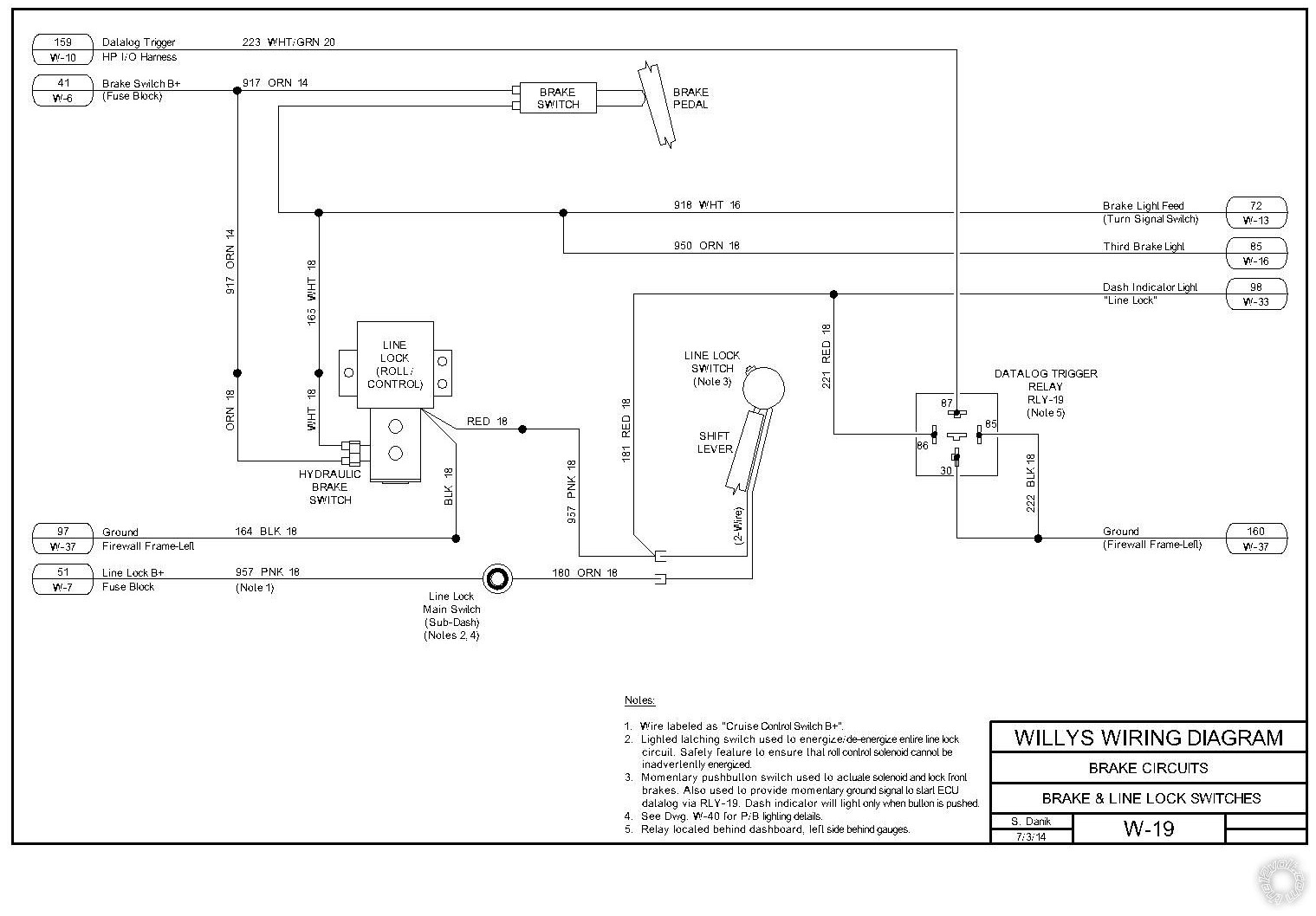
I have included my wiring diagrams for the setup. I used terminal #87 of the relay to connect to the ECU. I thought that this was isolating the ECU from any flyback voltage, either from the line lock solenoid, or the relay coil itself. The relay I am currently using does not have diode protection across the 85-86 coil terminals, which may also be part of the problem.
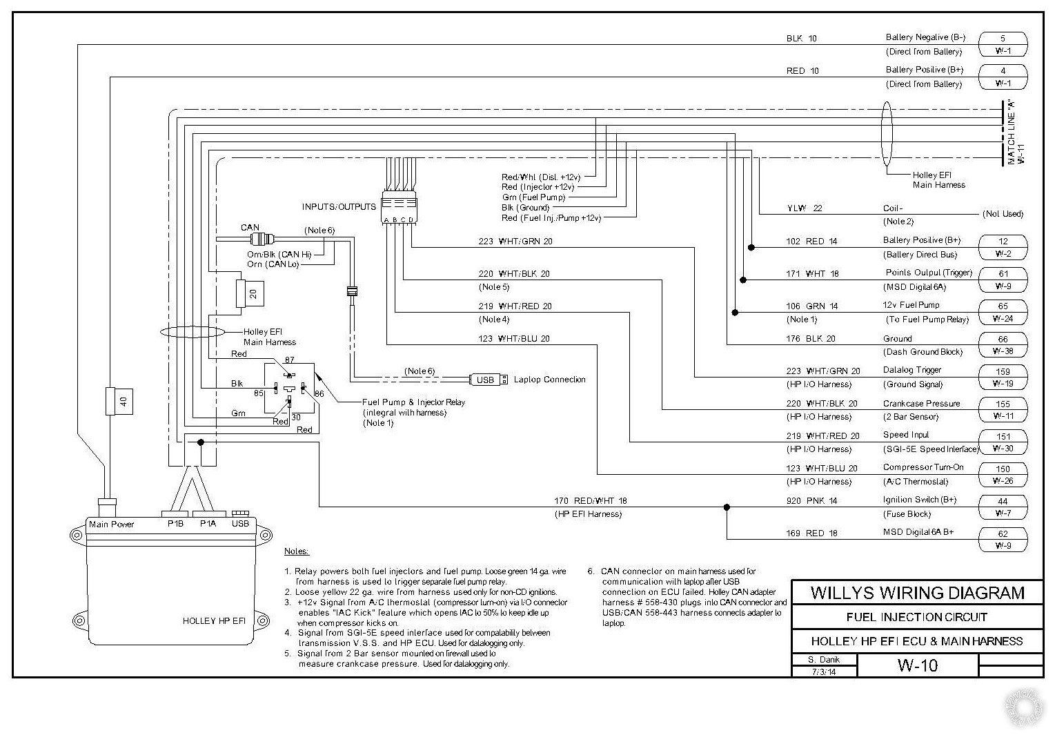
Please take a look at my schematics. The isolation relay is on diagram W-19 and labeled as RLY-19. Diagram W-10 shows the #223 wire connection to the HP I/O harness connector.
I believe that the way it is wired, the ECU would have been protected. What I would like to know is if there is any way that the ECU could have seen any spike from my using the line lock switch. Would it have been possible for a spike to travel from the common ground of terminals 85 and 30 back through the relay to terminal 87? Would it be possible for the connection between terminals 30 and 87 that only happens for a fraction of a second when the button is pushed also allow for a spike as the field collapses in both the line lock solenoid and relay coil as the button is released? Is some kind of diode protection required? As you can tell, my knowledge of electrical theory is just enough to be dangerous
.
A new ECU is on its way to me, but before I install it I want to make sure that my wiring did not cause the failure of my original unit.
Thanks to all for looking.
Steve


 Printable version


