the12volt.com spacer
icon

2000 Range Rover, Keyless Entry and Remote Start


Post ReplyPost New Topic
< Prev Topic Next Topic >
rovertech 
Member - Posts: 23
Member spacespace
Joined: January 08, 2011
Location: Virginia, United States
Posted: January 05, 2021 at 8:47 PM / IP Logged Link to Post Post Reply Quote rovertech
I have installed a Crimestopper rs7g-5 on my 2k Range Rover, for the engine to start the vehicle needs to see door unlock. I programmed the alarm to unlock, start and relock after start. to accomplish this, I used a separate solenoid into the internal lock unlock rod on driver's door. it worked as a charm or so I thought, 9 months later the force of the external add on lock solenoid damaged the internals of the BECM controlled driver's side lock. I have installed a replacement new driver's door latch and not wanting a repeat failure, I identified the lock unlock wires as orange black stripe and pink black stripe at door, when power is applied to any of these wires the lock unlock takes place accordingly, they rest at ground. to this I added 5 Wire Alternating 12 Volts Positive (Type C). it worked if I used the aftermarket remote, when I used the factory remote, it shorted the fuses to both the add on relays and door station on BECM (all other locks continued to work). I continued with type (D),this blew the fuse as soon as I insert it on fuse port. type (D) "a" and type (D) "b" with similar results.
This makes me think I need some sort of diode, is there an installer whom can guide me with the proper wiring. the factory remote needs to exist because if the vehicle decides to "superlock" it self, it bricks. if this was not the case I would not use factory remote.
thanks in advance.
lectricguy 
Copper - Posts: 359
Copper spacespace
Joined: March 18, 2008
Location: Rhode Island, United States
Posted: January 06, 2021 at 8:00 AM / IP Logged Link to Post Post Reply Quote lectricguy
Rovertech-
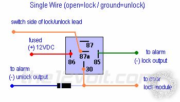
The door locks in the 2000 Range Rover are type "F", single wire door locks. Wiring should be as follows:
2000 Range Rover, Keyless Entry and Remote Start - Last Post -- posted image.
I hope this helps.
Lectric Guy
rovertech 
Member - Posts: 23
Member spacespace
Joined: January 08, 2011
Location: Virginia, United States
Posted: January 06, 2021 at 9:48 AM / IP Logged Link to Post Post Reply Quote rovertech
not being a nay sayer, I was reading the factory wiring diagram to identify the wiring and color routing. since I cannot paste on page I have loaded image on accessories under 2000 range rover. let me know if you come to the same conclusion. when testing, I had difficulty finding a dual signal purpose lock unlock wire thus could not use "F" diagram thus begun experimenting with the other diagrams.
thanks.
lectricguy 
Copper - Posts: 359
Copper spacespace
Joined: March 18, 2008
Location: Rhode Island, United States
Posted: January 06, 2021 at 11:58 AM / IP Logged Link to Post Post Reply Quote lectricguy
GREEN/RED (TYPE F) @ DRIVERS DOOR MODULE in DOOR
Pin 1 of M153 in the drawing which you uploaded.
Lectric Guy
rovertech 
Member - Posts: 23
Member spacespace
Joined: January 08, 2011
Location: Virginia, United States
Posted: January 11, 2021 at 3:39 PM / IP Logged Link to Post Post Reply Quote rovertech
Lectric, thanks for taking the time to review and respond. I don't do system installs to the public, but being a mechanic I play with my vehicles and to that my play time is very limited. today I revisited the lock issue on my land rover, I wired for type "F". these are my findings, when I use the factory fob all works well when I use the aftermarket nothing happens. when I probe the relay,at rest I have 12v on terminals 87a, 30 in addition to the fused 12v on terminal 86. the diode does it's work well and of course totally neutral (no signal positive or negative), the relay does click when any fob is used but again the function only takes place when using factory fob.
I probed the harness and found out that orange black stripe "OB" shows 12v when locking and orange pink stripe "OK" shows 12v when unlocking green red "GR" and blue red stripe "UR" show continuous ground no matter lock function, pink black stripe "KB" also shows 12 v signal when locking but if I wire it in to the circuit, it blows the fuse to the door out station on becm and tho the 12 v supply to relay circuitry.
for the moment, I have taken a breather from it. the alarm module is located behind the knee bolster under steering and if I need to reverse polarities, be it and I will have to remove and access to rewire. currently on the alarm/start module I have 12 volt signal on one leg when locking or unlocking.
thanks again, open to suggestions.
lectricguy 
Copper - Posts: 359
Copper spacespace
Joined: March 18, 2008
Location: Rhode Island, United States
Posted: January 12, 2021 at 8:11 PM / IP Logged Link to Post Post Reply Quote lectricguy
Rovertech-
In the drawing which you uploaded, the Green/Red (GR) wire between pin 1 of M153 (Left Front Door Lock Actuator) and Z243 pin 5 (Left Front Door Outstation module) is the correct wire. For the CDL switch shown, the Lock function is "0" and the Unlock function is "1" for the switch. When the door is locked, the module should see an open pulse, and a ground pulse for unlock. These this by sing a voltmeter, with the positive meter lead on +12V constant, and the negative meter lead on the door module wire. Your meter will read 12V when unlocking/unlocked with the CDL switch and no voltage when locking with the CDL switch. Not sure about your particular vehicle...the wire color may be different, you always need to test. If this is what you find, the type F relay circuit should work.
From your testing, the OB wire is the lock motor lead and OK is the unlock motor lead. You could use these wires with 2 relays (one for Lock and one for Unlock) to lock and unlock as follows:    
Pin 86 to fused +12V constant
Pin 85 to Remote start lock or unlock
Pin 87 to +12V fused constant
Pin 87A to Module side (Z243) of wire
Pin 30 to Motor side (M153) of wire
If your vehicle has a factory alarm, you may need to separately hook up factory alarm disarm when using the motors to lock and unlock.
Hope this helps.
Lectric Guy
rovertech 
Member - Posts: 23
Member spacespace
Joined: January 08, 2011
Location: Virginia, United States
Posted: January 12, 2021 at 8:17 PM / IP Logged Link to Post Post Reply Quote rovertech
thanks, I will give it a try. will report further findings.
rovertech 
Member - Posts: 23
Member spacespace
Joined: January 08, 2011
Location: Virginia, United States
Posted: January 19, 2021 at 4:35 PM / IP Logged Link to Post Post Reply Quote rovertech
Lectric, hi
here is an update which may explain why I was getting mixed results. apparently during testing I blew up the lock and unlock circuit in my remote start/alarm module. today during testing I noticed lack of signal from alarm module. I can hear click when activating but wiring fails to carry a signal. bottom line I need to yank the module from its mooring and investigate what is going on. I will update further upon findings.
Carlos.
lectricguy 
Copper - Posts: 359
Copper spacespace
Joined: March 18, 2008
Location: Rhode Island, United States
Posted: January 19, 2021 at 5:29 PM / IP Logged Link to Post Post Reply Quote lectricguy
Rovertech-
   Noted. Remote Start lock/unlock outputs from most recent units are fairly low current, so you need to be careful, and always test before connecting. Let us know what you find.
Lectric Guy

If you wish to post a reply to this topic, you must first login.
If you are not already registered, you must first register.

  Printable version Printable version Post ReplyPost New Topic
You cannot post new topics in this forum
You cannot reply to topics in this forum
You cannot delete your posts in this forum
You cannot edit your posts in this forum
You cannot create polls in this forum
You cannot vote in polls in this forum

  •  
Search the12volt.com
Follow the12volt.com Follow the12volt.com on Facebook
Friday, March 29, 2024 • Copyright © 1999-2024 the12volt.com, All Rights Reserved Privacy Policy & Use of Cookies
Disclaimer: *All information on this site ( the12volt.com ) is provided "as is" without any warranty of any kind, either expressed or implied, including but not limited to fitness for a particular use. Any user assumes the entire risk as to the accuracy and use of this information. Please verify all wire colors and diagrams before applying any information.

Secured by Sectigo
the12volt.com spacer
Support the12volt.com
Top
the12volt.com spacer