the12volt.com spacer
icon

2004 Mitsubishi Endeavor, Viper 350 Plus Alarm


Post ReplyPost New Topic
< Prev Topic Next Topic >
jaxzin 
Copper - Posts: 87
Copper spacespace
Joined: December 16, 2006
Posted: February 12, 2021 at 1:05 PM / IP Logged Link to Post Post Reply Quote jaxzin
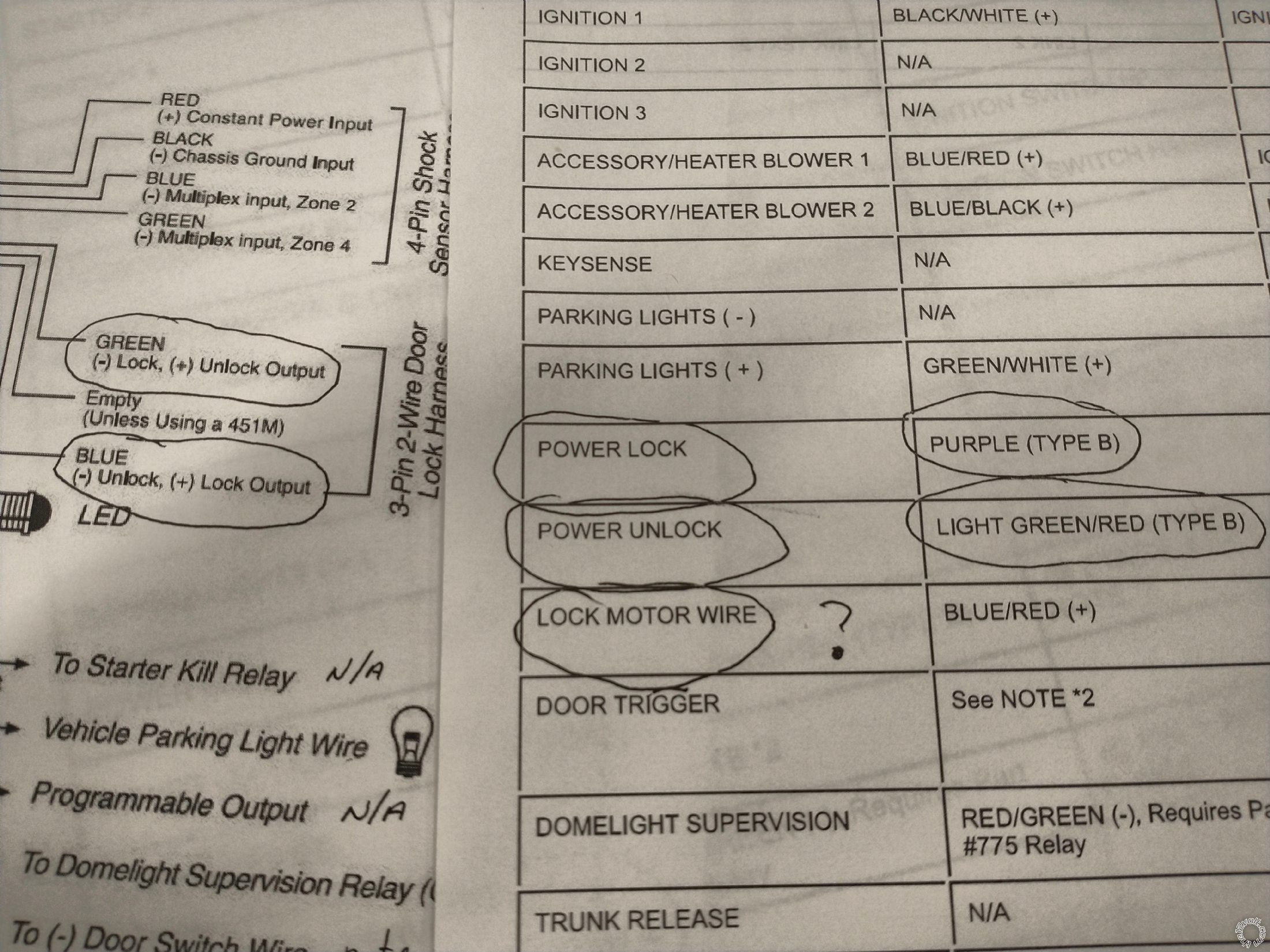
Getting ready to install a Viper 350 Plus alarm onto our 2004 Endeavor. have a couple of questions regarding the door lock / unlock wires. According to the picture below which are the wires, do I hook up......
Purple at the car to Green at the alarm
Light Green / Red at the car to Blue at the alarm?
Also, what do I hook to the Lock Motor wire?
2004 Mitsubishi Endeavor, Viper 350 Plus Alarm -- posted image.
lectricguy 
Copper - Posts: 359
Copper spacespace
Joined: March 18, 2008
Location: Rhode Island, United States
Posted: February 12, 2021 at 2:47 PM / IP Logged Link to Post Post Reply Quote lectricguy
"Purple at the car to Green at the alarm?" CORRECT.
"Light Green / Red at the car to Blue at the alarm?" CORRECT.
"Also, what do I hook to the Lock Motor wire?" NOT USED.
Since these Lock and Unlock alarm outputs are "flip-flop" type outputs, and provide a +12V drive when the opposite function is used (for example, the green alarm wire puts out Ground when lock is pressed, and +12V when unlock is pressed), it might be a good idea to protect the BCM by using a diode in series with each lock/unlock wire, band toward the alarm. A general purpose diode such as a 1N4001 is fine.
Please test the wires to make sure that you have the correct wire. Use a voltmeter, set to 20V DC scale (or whatever is close for your particular meter).   Place the red lead on +12V constant, black lead on the door lock wire under test. Now as you press the door lock switch, the purple wire in the car (that you suspect is the lock wire) should go to ground, causing the meter to show 12V. The same procedure should be used to test for for the unlock wire.
Never blindly connect to a color from a wire sheet--they are not always accurate.
Lectric Guy
jaxzin 
Copper - Posts: 87
Copper spacespace
Joined: December 16, 2006
Posted: February 22, 2021 at 7:49 AM / IP Logged Link to Post Post Reply Quote jaxzin
Thank you so much. Makes sense. I plan on using some Posi-Tap connectors to get my wires tapped into. Generally what gauage wire do vehicle systems have? 14-16 gauge?

If you wish to post a reply to this topic, you must first login.
If you are not already registered, you must first register.

  Printable version Printable version Post ReplyPost New Topic
You cannot post new topics in this forum
You cannot reply to topics in this forum
You cannot delete your posts in this forum
You cannot edit your posts in this forum
You cannot create polls in this forum
You cannot vote in polls in this forum

  •  
Search the12volt.com
Follow the12volt.com Follow the12volt.com on Facebook
Friday, March 29, 2024 • Copyright © 1999-2024 the12volt.com, All Rights Reserved Privacy Policy & Use of Cookies
Disclaimer: *All information on this site ( the12volt.com ) is provided "as is" without any warranty of any kind, either expressed or implied, including but not limited to fitness for a particular use. Any user assumes the entire risk as to the accuracy and use of this information. Please verify all wire colors and diagrams before applying any information.

Secured by Sectigo
the12volt.com spacer
Support the12volt.com
Top
the12volt.com spacer