Lets see if I understand.
2001 Dodge Dakota base truck - no power locks or power windows.
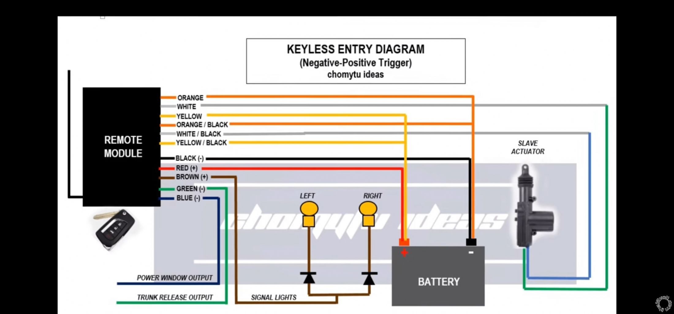
You are adding an aftermarket Remote Keyless Entry system that did not come with lock solenoids. You also purchased 2 two-wire door lock solenoid actuators with rods and mounting hardware. You won't be using the Truck Release and Power Window outputs.
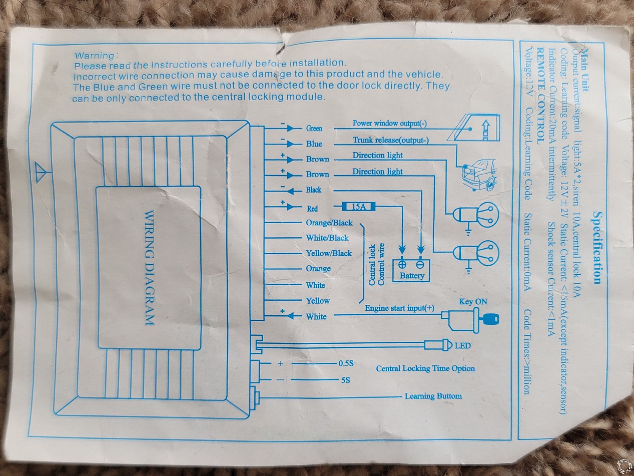
First question - Does the unit have internal lock relays?
From the wiring diagram, I believe it does. If they are typical relays, they can handle up to 30 Amps of current draw. That means that both actuator solenoids can be connect to the output wires. Standard gun style lock solenoid actuators draw less that 3 Amps each. If the top diagram is correct with its connections to the solenoids Green and Blue wires, then the top three wires (Orange, White and Yellow) are the Lock relay. The lower three wires (same colors with a Black stripe) are the Unlock relay. For comparison purposes the below list has the relay wires labeled in standard relay pin form :
White and White/Black are Pin 30 on their respective relays.
Orange and Orange/Black are Pin 87A on their respective relays.
Yellow and Yellow/Black are Pin 87 on their respective relays.
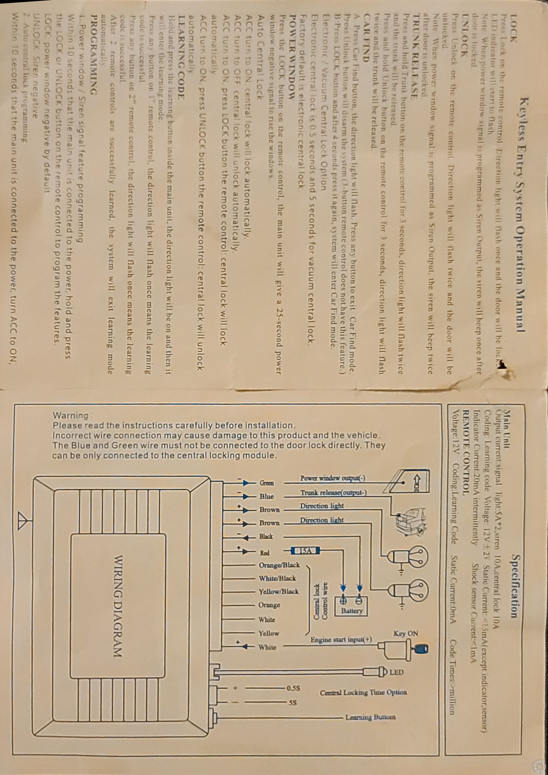
White output is Lock.
White/Black output is Unlock.
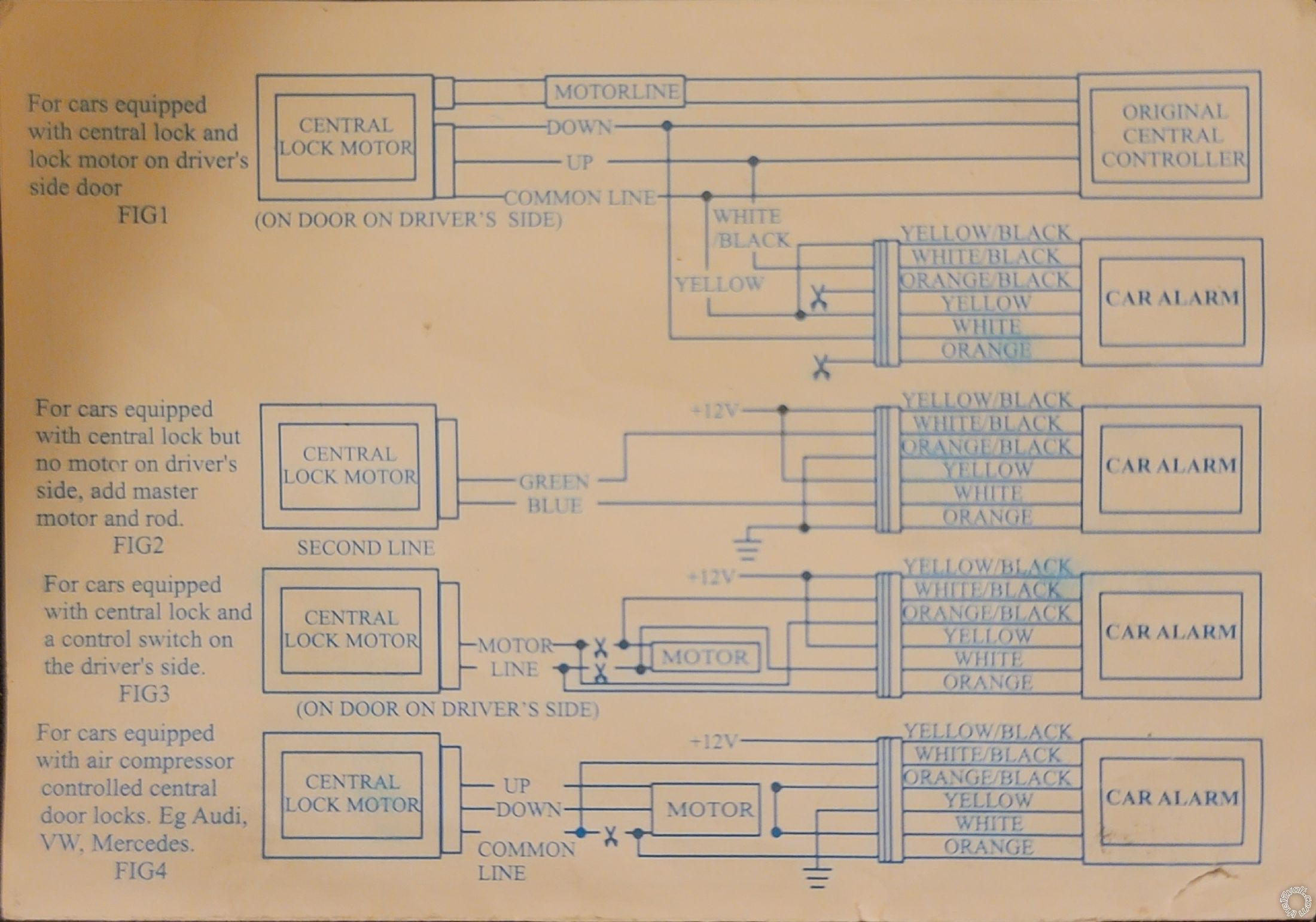
You can compare this to the added actuators door lock diagram on this site :
https://www.the12volt.com/doorlocks/multiple-wire-car-door-locks.asp#arp
For your two door application, I would fuse the lock relays wires going to +12V constant at 10 Amps.
Second question - power source
As far as the power source for this aftermarket system, I believe you could connect to the +12V constant wires at the ignition switch harness. Connect the Red wire to Pink/Black wire and the Yellow & Yellow/Black wires to the Red/Light Blue wire, fused at 10 Amps. Any solid frame, clean and rust free location under the dash for the Chassis Ground point will be fine.
Personally, I would lay this whole system out on a bench and wire up the power, ground and lock actuators first. Make any necessary programming changes and test everything. You will see how the actuators move with the remotes button presses and better understand how the solenoids and rods must be connected inside the doors.
This system is similar to a more common and available system used in the states, the Avital 2101L. For comparison purposes, you can find its' install guide in the Downloads section. It has better lock wiring diagrams but the wire colors are different and there is an error in the manual. The H1/6 White/Black wire is actually relay Pin 87A.
Soldering is fun!


 Printable version


