


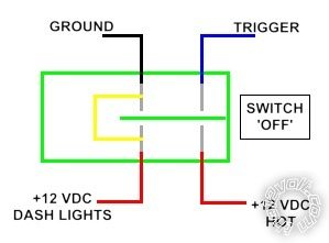
 The last pictures show the connections when switch is OFF and ON. In the diagrams,
the Switch is GREEN
The LED is YELLOW
The Trigger wire to the Relay is BLUE
Ground is BLACK.
RED 1 goes to the dash lights through a diode and resistor in series so they 1) lower the brightness of the LED, 2) block the full +12 VDC RED 2 from flowing badk theough RED 1 to the lights.
The resistor and diode connected to RED 1 are not shown.
I need to know the value of the resister to diminish the LEDs brightness to about 1/2 when the switch is off, and the number and orientation of the diode to keep the full voltage of RED 2 from flowing back to the lighting system.
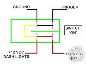
When the switch is turned ON, RED 2 to RED 1 are connected, as are GROUND and TRIGGER.
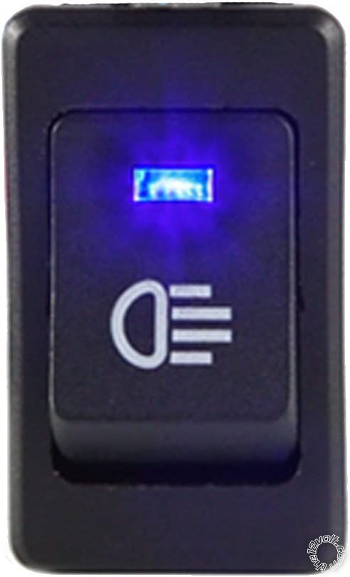
Any help is appreciated. It's been years since i've done anything like this. I want to be able to see the indicators of the switches at night, but not at full brightness until they're turned on.
Then you everyone.
James
The last pictures show the connections when switch is OFF and ON. In the diagrams,
the Switch is GREEN
The LED is YELLOW
The Trigger wire to the Relay is BLUE
Ground is BLACK.
RED 1 goes to the dash lights through a diode and resistor in series so they 1) lower the brightness of the LED, 2) block the full +12 VDC RED 2 from flowing badk theough RED 1 to the lights.
The resistor and diode connected to RED 1 are not shown.
I need to know the value of the resister to diminish the LEDs brightness to about 1/2 when the switch is off, and the number and orientation of the diode to keep the full voltage of RED 2 from flowing back to the lighting system.
When the switch is turned ON, RED 2 to RED 1 are connected, as are GROUND and TRIGGER.
Any help is appreciated. It's been years since i've done anything like this. I want to be able to see the indicators of the switches at night, but not at full brightness until they're turned on.
Then you everyone.
James
If you wish to post a reply to this topic, you must first login.
If you are not already registered, you must first register.
 Printable version


| You cannot post new topics in this forum You cannot reply to topics in this forum You cannot delete your posts in this forum You cannot edit your posts in this forum You cannot create polls in this forum You cannot vote in polls in this forum |

| Search the12volt.com |
Follow the12volt.com 
Saturday, May 23, 2026 • Copyright © 1999-2026 the12volt.com, All Rights Reserved • Privacy Policy & Use of Cookies

Saturday, May 23, 2026 • Copyright © 1999-2026 the12volt.com, All Rights Reserved • Privacy Policy & Use of Cookies
Disclaimer:
*All information on this site ( the12volt.com ) is provided "as is" without any warranty of any kind, either expressed or implied, including but not limited to fitness for a particular use. Any user assumes the entire risk as to the accuracy and use of this information. Please
verify all wire colors and diagrams before applying any information.
