the12volt.com spacer
icon

Spy LC095A Remote Starter, Volvo XC90


Post ReplyPost New Topic
< Prev Topic Next Topic >
rescape 
Member - Posts: 4
Member spacespace
Joined: December 29, 2022
Location: Quebec, Cameroon
Posted: December 29, 2022 at 10:38 PM / IP Logged Link to Post Post Reply Quote rescape
Hello guys,
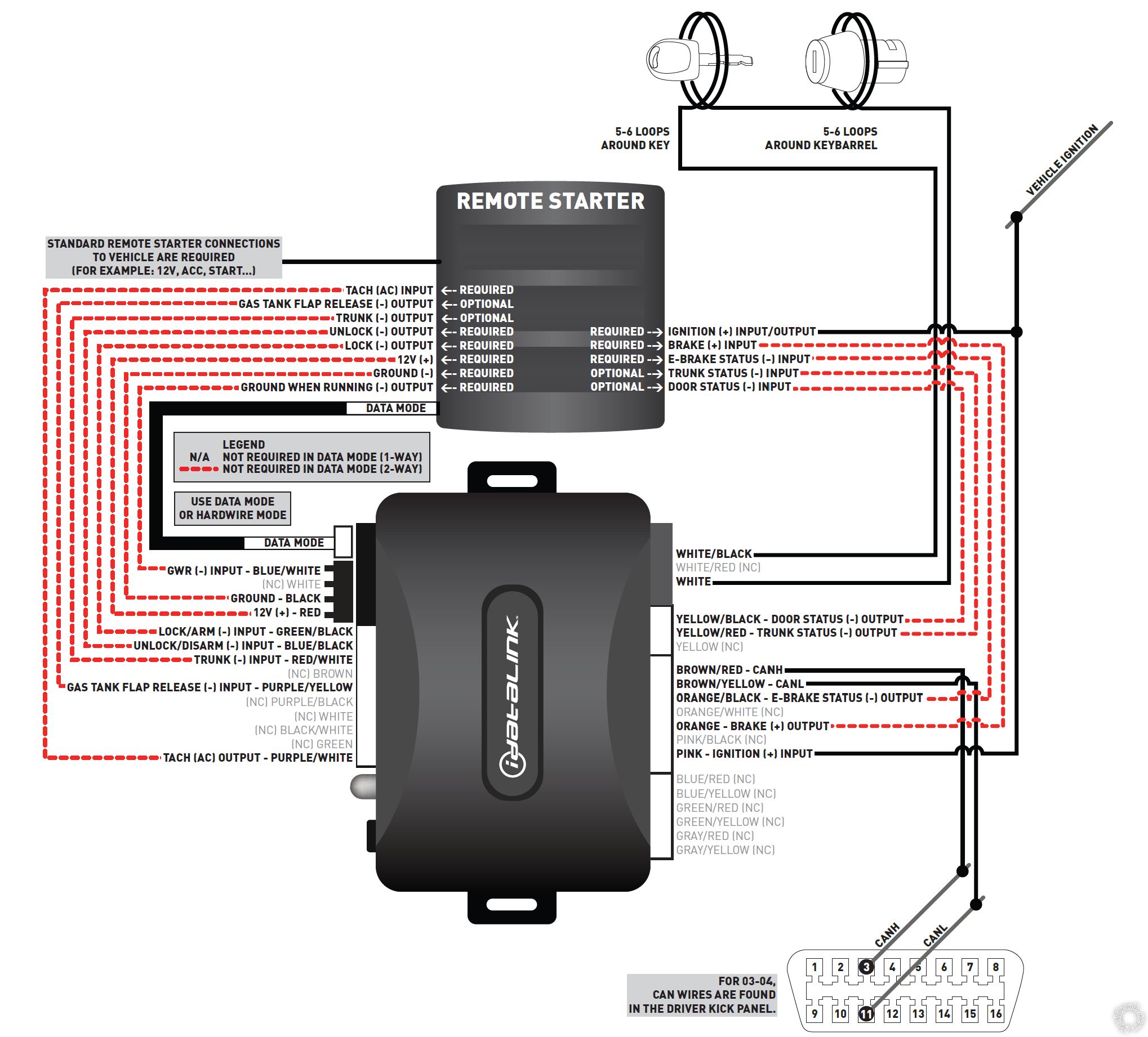
Sorry for my bad english, it's not my first langage. I'm trying to install LC095A Spy remote starter associate with idatalink dbi-al bypass module (Wiring mode, not data) on my volvo xc 90, 3.2L with automatic transmission. Unfortunatly i have two issues:
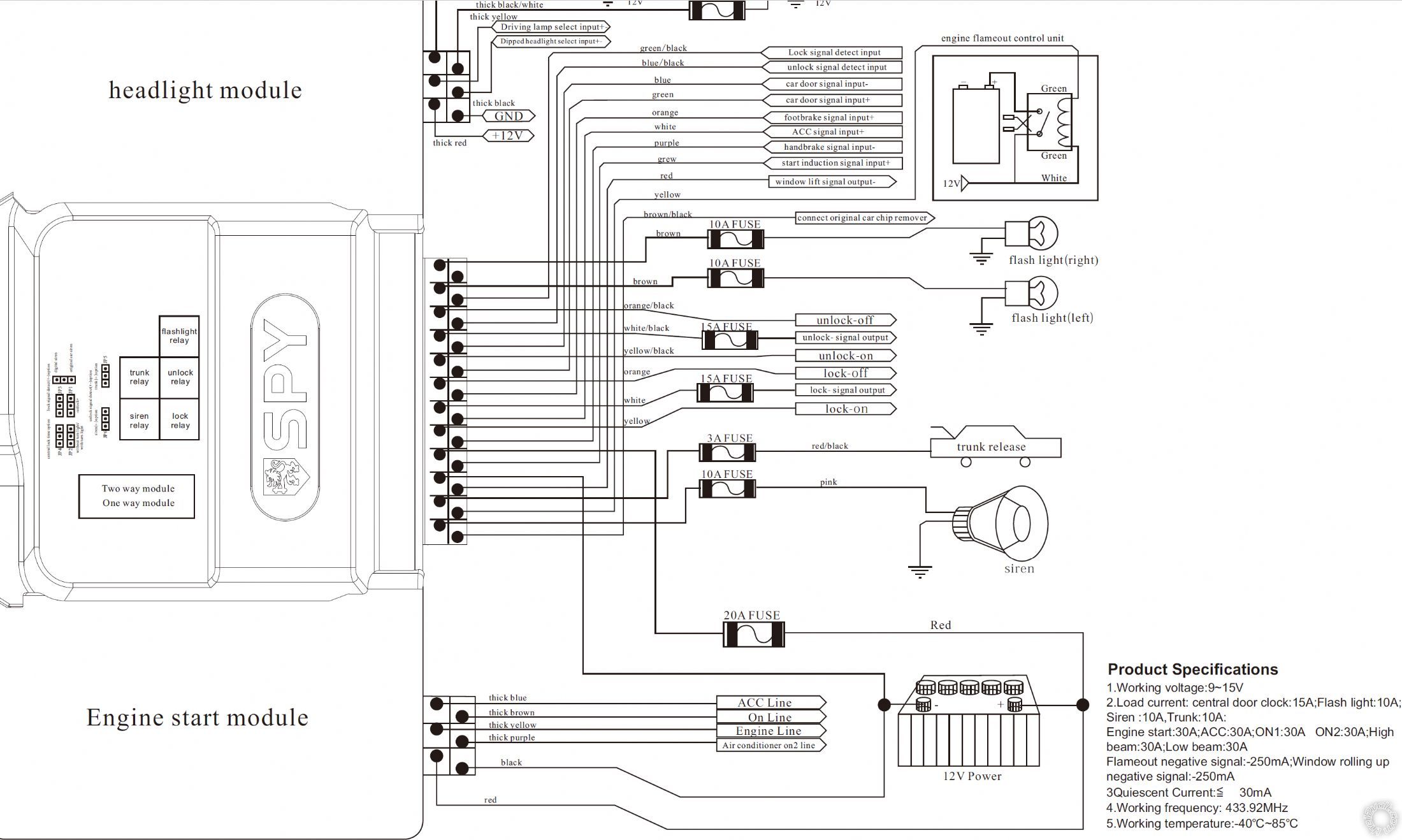
1. i need to plug the key in the ignition cylinder to make remote starter working, i learn here that the keysene is require to make remote starter works. The issue is that, as you can see in the wiring diagram of immobiliser or remote starter i don't see one wire name to connect to keysene of the car.
2. when i plug the key in the iginition and try a remote start, the car start as well, but shutdown around 5s later, restart and shutdown twice.
Do you have one wire to advise me to connect to the keysense of my car, to enable remote start ?
What can explain the shutdown of the car, just after the car start? i suspect the "start induction signal input+" wire that i connect to tach wire of idatalink, but i'm not shure.
Find, attached, the wiring diagram of remote starter and bypass module
Thanks.
Spy LC095A Remote Starter, Volvo XC90 -- posted image.
my car: Volvo xc 90, automatic transmission, 3.2L
kreg357 
Platinum - Posts: 7,783
Platinum spaceThis member has made a donation to the12volt.com. Click here for more info.spaceThis member has been recognized as an authority in Electrical Theory. Click here for more info.spaceThis member has been recognized as an authority in Mobile Security and Convenience. Click here for more info.spacespace
Joined: January 30, 2009
Location: Pennsylvania, United States
Posted: December 30, 2022 at 7:28 PM / IP Logged Link to Post Post Reply Quote kreg357
Greetings,
You might have three problems. Aside from the Keysense and Tach issue, you might also have a problem with GWR. Remember that inserting a key to get keysense is also providing the chip info to the ignition switch antenna.
First lets check the Spy module for a GWR output. The nomenclature is non-standard but the Blown/Black wire called "connect original car chip remover" might be GWR. Test to see if it is a (-) output that starts just before the R/S sequence outputs the thick Brown "ON" wire. It should stay (-) the entire R/S runtime. If that is what this wire does, then it is the GWR wire and goes to the ADS AL-CA Blue/White wire. This will turn on the ADS AL-CA White and White/Black wires for the Key wrap at the correct time to supply the XC90 the needed key chip info. If you are still having issues with the transponder chip info re-check your key and switch wire-wraps.
Issue 2 : Keysense
Due to limitation with your R/S system, there is no easy way to output a (+) Keysense signal without some 30/40 Amp SPDT Relays. Basically, you are going to use the thick Brown "ON" output to control two relays*, each with their own fused +12V input. One relays isolated output will go to the vehicles IGN wire just like before and the other relays output will go to the Keysense wire. Using two relays and their isolated outputs will allow the car to work normally and accomplish a R/S.
Issue 3 : Three R/S attempts and quit
I'm guessing that the module is in Tach Mode and needs to see a valid Tach signal. This might be the "engine flameout control unit" circuit. Or it could be the input wire called "start induction signal". This is a common problem with these "offshore" R/S units. You could try connecting the ADS AL-CA Purple/White Tach output to the Grey "start induction signal" wire and do a Tach Learn. A possible solution if the Volvo has "one-touch-start" where you can just turn the ignition key to START and release quickly and allow the ECM to control the crank time. Does the SPY have any programming options other that Tach Mode? Tach-less, fixed, etc?
My overall recommendation would be to bin the SPY unit and get a Compustar CS4900-s.
* Relay wiring
SPY thick Brown to Pin 86 on both relays
Chassis Ground to Pin 85 on both relays
Fused +12V constant to both relays at Pin 87
Relay 1 Pin 30 to XC90 Ignition
Relay 2 Pin 30 to XC90 Keysense
Soldering is fun!
rescape 
Member - Posts: 4
Member spacespace
Joined: December 29, 2022
Location: Quebec, Cameroon
Posted: January 01, 2023 at 12:09 PM / IP Logged Link to Post Post Reply Quote rescape
Thanks alot kreg357 and happy new year,
I confirm that the brown/black wire named "connect original car chip remover" is the GWR.
I'm confuse about the wiring configuration for one of the two relay, because as you can see on spy wiring diagram, there is no connection with the ON (IGN) wire, so what i did with that relay is as ask in the SPY wiring diagram. So this is my first relay wiring (i can change if you confirm that it's not correct to have all i need)
Pin 86 connected to +12v
Pin 85 connected to yellow wire (going throw engine flameout control unit) of the SPY
i cut the start wire
Pin 30 and 87a connected to each size of the start wire
my confusion is because you say "One relay isalated outpout will go to the vehicle IGN wire just like before", so may i change my original wire?
For the second relay, may a use a different +12v imput wire from the first relay?
Issue 3:
I have allready connected the "start induction signal" to the tach purple/white wire of the ADS AL-CA before having that issue.
in a manual of another remote starter model of SPY, it's ask in case of missing the tach wire to connect "start induction signal" to ignition1, fuel or oil pump. Do you think, this should work with this model ?
The volvo did'nt have a push to start, but SPY provide one push to start button to connect with the remote starter if i want to upgrade.
Thanks again for your time.
my car: Volvo xc 90, automatic transmission, 3.2L
kreg357 
Platinum - Posts: 7,783
Platinum spaceThis member has made a donation to the12volt.com. Click here for more info.spaceThis member has been recognized as an authority in Electrical Theory. Click here for more info.spaceThis member has been recognized as an authority in Mobile Security and Convenience. Click here for more info.spacespace
Joined: January 30, 2009
Location: Pennsylvania, United States
Posted: January 01, 2023 at 2:57 PM / IP Logged Link to Post Post Reply Quote kreg357
Hi,
Without a full install manual I might be at a disadvantage.   I'm also guessing with a 2005 - 2014 XC90.
My thoughts are :
SPY thick Blue to XC90 Blue ACC1
SPY thick Brown to external relay control *
SPY thick Yellow to Yellow/White Starter
SPY thick Purple to Purple ACC2
* Relay wiring - 30/40 Amp SPDT relays with 5 pin harness
SPY thick Brown to Pin 86 on both relays
Chassis Ground to Pin 85 on both relays
Fused +12V constant to both relays at Pin 87 **
Relay 1 Pin 30 to XC90 Ignition Blue/Red
Relay 2 Pin 30 to XC90 Keysense Yellow
** can be from the same +12V source if capable. There are two Red wires in the DKP that are rated at 50 Amps each.
It looks like the APY Grey "Start induction signal" is looking for a (+) input. As previously mentioned, this is the weak point of the off-shore R/S units. The purpose of a Tach signal is to determine when the engine is running and how long to crank it. Over and under crank each have their own problems. If the engine starts and then shuts down 5 seconds later, the crank time is long enough and you could try connecting the Grey wire to the XC90's IGN wire. You might get a bit of over-crank with a warm engine or it might not start a very cold engine on the first or second try. Assuming it adds crank time with each retry, it might work OK.
Cheers
Soldering is fun!
rescape 
Member - Posts: 4
Member spacespace
Joined: December 29, 2022
Location: Quebec, Cameroon
Posted: January 04, 2023 at 10:26 PM / IP Logged Link to Post Post Reply Quote rescape
Hi,
here is the full install manual
Install manual
I need to order a SPDT relay first, because the RS come with a 4 pins.
I check how the keysense of the car works, when there is no key in the cylinder i have a ground on the keysense wire but when key is insert, i have 12v. Is it the normal? because i read some where that it should be the opposite. i.e ground when the key is inside ignition cylinder, a 12v when no key insert.
thanks
my car: Volvo xc 90, automatic transmission, 3.2L
kreg357 
Platinum - Posts: 7,783
Platinum spaceThis member has made a donation to the12volt.com. Click here for more info.spaceThis member has been recognized as an authority in Electrical Theory. Click here for more info.spaceThis member has been recognized as an authority in Mobile Security and Convenience. Click here for more info.spacespace
Joined: January 30, 2009
Location: Pennsylvania, United States
Posted: January 05, 2023 at 3:00 AM / IP Logged Link to Post Post Reply Quote kreg357
The info I have confirms your Keysense wire test results. Keysense goes to (+) when a key is inserted. That is also inline with the added relays and wiring I supplied above. The added relay will output a (+) signal that the Keysense wire meeds.
Soldering is fun!
rescape 
Member - Posts: 4
Member spacespace
Joined: December 29, 2022
Location: Quebec, Cameroon
Posted: January 17, 2023 at 11:18 AM / IP Logged Link to Post Post Reply Quote rescape
Hello Kreg357,
I have wire my relays,i have a keysense voltage as it should be, but i think i can't bypass the immobiliser. I check the ALCA module, the green led blink as it should during the remote start process but the car don't start. After wired the keysense, i was thinking that maybe the signal came late, and i connect the keysense wire direct to a +12v to simulate a key alwayse in the ignition without success. I put the key close tho the ignition cylinder and try a remote start, but it didn't work. Do you think that it is really a immobiliser bypass issue? Note: when i plug the key inside the cylinder the car start without any issue.
Thanks.
my car: Volvo xc 90, automatic transmission, 3.2L
kreg357 
Platinum - Posts: 7,783
Platinum spaceThis member has made a donation to the12volt.com. Click here for more info.spaceThis member has been recognized as an authority in Electrical Theory. Click here for more info.spaceThis member has been recognized as an authority in Mobile Security and Convenience. Click here for more info.spacespace
Joined: January 30, 2009
Location: Pennsylvania, United States
Posted: January 18, 2023 at 5:40 PM / IP Logged Link to Post Post Reply Quote kreg357
Double check the relay output wire going to Keysense to verify that it does have +12V during a R/S. Your constant +12V test proved that the issue is with the transponder chip info transfer. You should be able to get a R/S if the key is help in just the right spot by the ignition switch key barrel.
It sounds like an issue with the transponder chip and key-wrap. It's important that the key wrap wires are secured in the correct position on the key and around the ignition switch key barrel.
Soldering is fun!

If you wish to post a reply to this topic, you must first login.
If you are not already registered, you must first register.

  Printable version Printable version Post ReplyPost New Topic
You cannot post new topics in this forum
You cannot reply to topics in this forum
You cannot delete your posts in this forum
You cannot edit your posts in this forum
You cannot create polls in this forum
You cannot vote in polls in this forum

  •  
Search the12volt.com
Follow the12volt.com Follow the12volt.com on Facebook
Friday, April 19, 2024 • Copyright © 1999-2024 the12volt.com, All Rights Reserved Privacy Policy & Use of Cookies
Disclaimer: *All information on this site ( the12volt.com ) is provided "as is" without any warranty of any kind, either expressed or implied, including but not limited to fitness for a particular use. Any user assumes the entire risk as to the accuracy and use of this information. Please verify all wire colors and diagrams before applying any information.

Secured by Sectigo
the12volt.com spacer
Support the12volt.com
Top
the12volt.com spacer