Thanks for both of you guys' input chev and kreg.
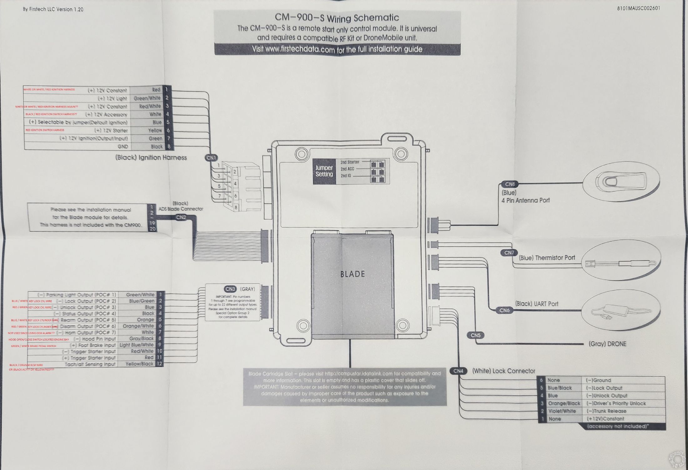
So could you guys check this wiring diagram of the CompuStar CM900 Module I have. There are some things that I am still confused about. The ones I have question marks are what I'm not sure. The ones I left BLANK are the ones I'm not sure what wire too hook it up to.
I am not sure how to proceed with what you are recommending of applying (-) GWR to the keysense wire. First of all, would you explain what GWR means? Does that mean "ground wire"? Can I just hook up one of the CompuStar output wire like the (-) Status output pin 4 on the CN3(Gray) to temporarily apply (-) to keysense while i remote start it without me being inside the car yet?
Note that I did use the remote color wiring information found here at the12v.com as well as a wiring diagram that I pulled from my ALLDATA.
EDIT: Just realized that the labels I made on the picture is too small to be able to read after being uploaded. So I'll just type it out below. Please do correct me where I'm wrong in my wiring, and like I said, BLANK/EMPTY means I'm confused how to wire - so assistance is greatly appreciated and needed.
CompuStar Module CN1Vehicle OEM Harness
1) +12v Constant -------------------------------> White/Red Ignition Switch Harness
2) +12v Light----------------------------------->
3) +12v Constant--------------------------------> White/Red Ignition Switch Harness (Again???)
4) +12v Accessory-------------------------------> Black/Red Ignition Switch Harness ???
5) + Selectable by Jumper(Default Ignition)----->
6) +12v Ignition(Output/Input)------------------>
CompuStar Module CN3(GRAY) Vehicle OEM Harness
1) - Parking Light Output----------------------->
2) - Lock Output--------------------------------> Blue/White Key Lock Cyl Wire
3) - Unlock Output------------------------------> Red/Green Key Lock Cyl Wire
4) - Status Output------------------------------>
5) - Rearm Output-------------------------------> Blue/White Key Lock Cyl Wire
6) - Disarm Output------------------------------> Red/Green Key Lock Cyl Wire
7) - Horn Output-------------------------------->
8) - Hood Pin Input-----------------------------> Hood Open/Close Switch Located In Engine Bay
9) + Foot Brake Input---------------------------> Green/White Brake Pedal Switch
10) - Trigger Starter Input--------------------->
11) + Trigger Starter Input--------------------->
12) Tach/Alt Sensing Input----------------------> Black/Orange ECM Wire?? OR BLACK AC?? OR YELLOW/RED???
 2000 Toyota Camry


 Printable version


