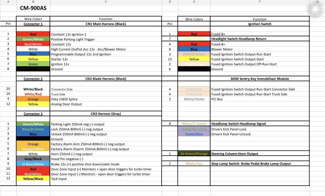
Just saw this. I'm very confused with your chart. If I'm interrupting it correctly, a lot of it seems wrong.
First we could use some more info on your truck. I think it's a 2004 Dodge RAM 3500 with a diesel engine and you are installing a Compustar CM900-as with a Blade-AL cartridge.
The CM900-as is for auto trans only so your truck must not have a manual trans.
Did your truck come with an OEM (factory) Alarm system?
Did you flash the Blade-AL with the CH6 firmware?
Are you following the Type3 wiring in the Install Guide #66308?
Did the Blade-AL program correctly as per the guide?
Here are two things that should help. As you found out, the Blade-AL CH6 guide only shows the connections necessary for the Blade-AL functions as shown at the beginning of the guide. It does not show the necessary CM900-as connections. While they are not the same take a look at the CMHCXA0 install guide for your truck. It will show what iDatalink believes are necessary with wire colors and locations. Here is a link to the guide :
https://images.idatalink.com/vehicle-install-guides/Guides/394/341/5088/EN/RSA-CH6-[CMHCXA0]-(Dodge_Ram_2004_5088)-EN-H_20230514_193524.pdf
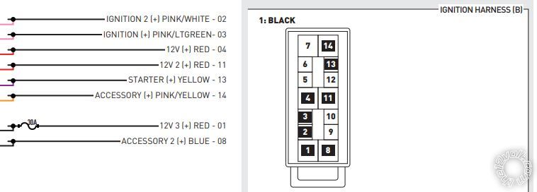
Notice the ignition wires they used, IGN1, IGN2, ACC1, ACC2 and Starter1. You probably are not correctly powering one of those signals if you need the key inserted and turned to ON to get a R/S.

You can change the programming of an unused POC wire to an ACC(-) output to control a 30/40 Amp SPDT Relay to provide for the trucks ACC2 wire.
The CN1 wiring should look like this :
CN1 ....................................................... Black IGN Harness
Pin 1 Red - Constant 12V Red @ Pin 4
Pin 2 Green/White - Programmable Output use for Parking Light MUX control relay
Pin 3 Red/White - Constant 12V Red @ Pin 11
Pin 4 White - Accessory 12V positive (+) Pink/Yellow @ Pin 14
Pin 5 Blue - Programmable Output IGN2 Pink/White @ Pin 2
Pin 6 Yellow - Starter 12V positive (+) .... Yellow @ Pin 13
Pin 7 Green - Ignition 12V positive (+) .... Pink/Light Green @ Pin3
Pin 8 Black - Ground negative (-) input ..... Chassis Ground
You will need another 30/40 Amp SPDT relay for ACC2 controlled by that re-assigned POC wire.
Soldering is fun!
 Printable version


 You can change the programming of an unused POC wire to an ACC(-) output to control a 30/40 Amp SPDT Relay to provide for the trucks ACC2 wire.
The CN1 wiring should look like this :
CN1 ....................................................... Black IGN Harness
Pin 1 Red - Constant 12V Red @ Pin 4
Pin 2 Green/White - Programmable Output use for Parking Light MUX control relay
Pin 3 Red/White - Constant 12V Red @ Pin 11
Pin 4 White - Accessory 12V positive (+) Pink/Yellow @ Pin 14
Pin 5 Blue - Programmable Output IGN2 Pink/White @ Pin 2
Pin 6 Yellow - Starter 12V positive (+) .... Yellow @ Pin 13
Pin 7 Green - Ignition 12V positive (+) .... Pink/Light Green @ Pin3
Pin 8 Black - Ground negative (-) input ..... Chassis Ground
You will need another 30/40 Amp SPDT relay for ACC2 controlled by that re-assigned POC wire.