the12volt.com spacer
icon

Remote Start Wiring, 2008 Toyota Prius


Post ReplyPost New Topic
< Prev Topic Next Topic >
dacker 
Copper - Posts: 60
Copper spacespace
Joined: May 08, 2017
Location: Alabama, United States
Posted: January 21, 2024 at 10:40 PM / IP Logged Link to Post Post Reply Quote dacker
Apparently it is an al here was the box it came in Remote Start Wiring, 2008 Toyota Prius - Page 4 -- posted image.
dacker 
Copper - Posts: 60
Copper spacespace
Joined: May 08, 2017
Location: Alabama, United States
Posted: January 21, 2024 at 10:49 PM / IP Logged Link to Post Post Reply Quote dacker
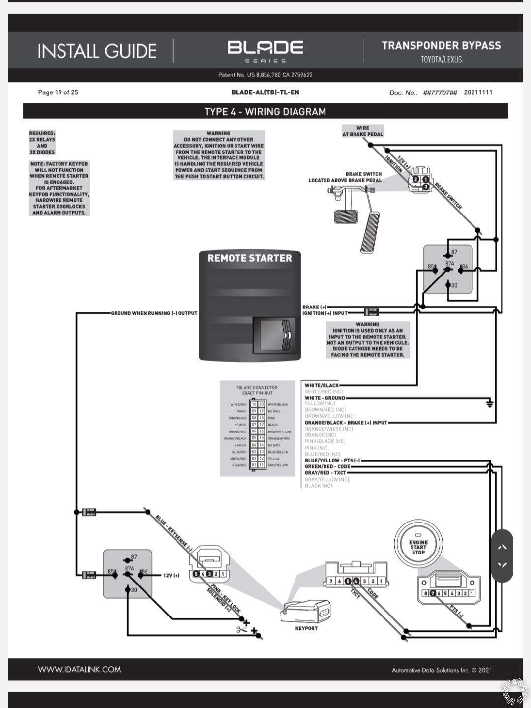
This was the install guide I used Remote Start Wiring, 2008 Toyota Prius - Page 4 -- posted image.
kreg357 
Platinum - Posts: 7,802
Platinum spaceThis member has made a donation to the12volt.com. Click here for more info.spaceThis member has been recognized as an authority in Electrical Theory. Click here for more info.spaceThis member has been recognized as an authority in Mobile Security and Convenience. Click here for more info.spacespace
Joined: January 30, 2009
Location: Pennsylvania, United States
Posted: January 22, 2024 at 7:45 AM / IP Logged Link to Post Post Reply Quote kreg357
While they used the more expensive Blade-AL cartridge, the functionality and wiring is the same.
I'm not really sure where you are right now.
Do you have all the wiring as per the Type 4 diagram and my CM900 posted list?
Did all of the vehicle wire colors and locations match?
Does the vehicle still start and operate normally?
Did the Blade program exactly as per the install guide Type 4 steps?
Do the Compustar remotes control the door locks and flash the parking lights?
Did you change the 2-10 option to 4?
Does pressing and holding the R/S button 3 seconds do anything (Brake lights should come ON)?
Soldering is fun!
dacker 
Copper - Posts: 60
Copper spacespace
Joined: May 08, 2017
Location: Alabama, United States
Posted: January 22, 2024 at 10:32 PM / IP Logged Link to Post Post Reply Quote dacker
Hey sorry for the delay I got slammed with another work issue but I got around to checking everything and here is where I am.
Do you have all the wiring as per the Type 4 diagram and my CM900 posted list? Yes except for Pin 2 Green/White - Programmable Output.............BROWN   @ FUSE BOX, TOP LEFT CONN., PIN 10 I am not sure how to get to this and the fuse box runs parallel to the ground so I am not sure what exactly I am looking for or hooking up.
Did all of the vehicle wire colors and locations match? Yes
Does the vehicle still start and operate normally? Yes, if you are referring to me putting the key in the slot and foot on the brake and pushing the PTS button.
Did the Blade program exactly as per the install guide Type 4 steps? Yes
Do the Compustar remotes control the door locks and flash the parking lights? No and I think I read on your post where it said parking lights were not used. When trying to control the locks with the computer remote the brain box does click and send a (–) signal to either the lock or unlock wire whichever button I have hit but the locks do not lock or unlock.
Did you change the 2-10 option to 4? No because I am limited to only the 1st 4 options in the menu without the op500 the best I can tell
Does pressing and holding the R/S button 3 seconds do anything (Brake lights should come ON)? Brake lights do not come on and the led flashes blue 3 times the MFD powers up and I hear clicking from the RS and the led turns red for a second and the just blinks blue 3 times and stops then blinks blue 3 times and stops and so on. It will then click again led turn red and cycle repeats itself. If I do this with the door open when I hold the RS button for 3 seconds and the led blinks blue 3 times the car beeper starts immediately beeping like it will do if you leave the key in the ignition and open the door to get out so to remind you not to leave the key in the slot.
I also checked the wire at the PTS button and it gets a negative pulse when trying to start the car just like if you were pushing the button manually but it never powers on. I double checked all the diodes were facing the correct direction as well and they are.
kreg357 
Platinum - Posts: 7,802
Platinum spaceThis member has made a donation to the12volt.com. Click here for more info.spaceThis member has been recognized as an authority in Electrical Theory. Click here for more info.spaceThis member has been recognized as an authority in Mobile Security and Convenience. Click here for more info.spacespace
Joined: January 30, 2009
Location: Pennsylvania, United States
Posted: January 23, 2024 at 5:56 PM / IP Logged Link to Post Post Reply Quote kreg357
Thanks for the update.
The fact that the Parking Light wire is not hooked up is not causing any problems. It would provide a nice visual indication of functions and possible error codes. The clicking you hear is the controllers internal (+) Parking Light relay so the remotes are paired and functional. I would double check the vehicle lock wires. I think I described the test procedure during the 2010 Prius install using a DMM and the drivers door key lock cylinder. You will need to set the CM900 to a double Unlock pulse (1-4 Option 2).
The fact that the car is still operational with a regular start-up is good news.
It also appears that the Blade cartridge programmed properly.
It is possible to change CM900 options using the remotes. The two Special Option Groups can only be changed with the OP-500 Programmer but the other 4 Groups can be changed with the remotes. It requires a bit of effort as timing is critical. The full CM900 Install Guide is in the Downloads section of this site.
The instructions for your 4 button 1 way remotes are at the bottom of Page 47. Use the tables included with the you system as some options have changed /enhanced. The two you should change are the same.
I'm pretty sure the Brake lights should come on during a R/S attempt. You should check those connections/relay to ensure all is correct. Basically, the White wire of the 20 Pin Blade plug has Chassis Ground. When the Blade cartridge see a R/S request it outputs that Chassis Ground signal on the White/Black wire. This turns on the "Brake Relay" and connects Pin 87 to Pin 30. Pin 87 has +12V on it and this 12V gets output on Pin 30. Pin 30 is connected to the vehicle Brake wire simulating a Brake Pedal press. The relay wiring also prevents the CM900 from seeing the +12V on the Brake wire which would prevent or shutdown a R/S.
Soldering is fun!
dacker 
Copper - Posts: 60
Copper spacespace
Joined: May 08, 2017
Location: Alabama, United States
Posted: January 24, 2024 at 9:32 PM / IP Logged Link to Post Post Reply Quote dacker
You got to love electronics. Somehow the white #9 ground pin off the blade plug had gotten pushed back out of the connector and wasn't making a connection this whole time 🙄. We are 100% now locks, lights, start and all. Again Kreg357 you are a true lifesaver I couldn't have done either of these without you my friend!!!!
kreg357 
Platinum - Posts: 7,802
Platinum spaceThis member has made a donation to the12volt.com. Click here for more info.spaceThis member has been recognized as an authority in Electrical Theory. Click here for more info.spaceThis member has been recognized as an authority in Mobile Security and Convenience. Click here for more info.spacespace
Joined: January 30, 2009
Location: Pennsylvania, United States
Posted: January 24, 2024 at 9:55 PM / IP Logged Link to Post Post Reply Quote kreg357
Great news! Thanks for the update. Enjoy your hard work with a warm car!
Soldering is fun!
Page of 4

If you wish to post a reply to this topic, you must first login.
If you are not already registered, you must first register.

  Printable version Printable version Post ReplyPost New Topic
You cannot post new topics in this forum
You cannot reply to topics in this forum
You cannot delete your posts in this forum
You cannot edit your posts in this forum
You cannot create polls in this forum
You cannot vote in polls in this forum

  •  
Search the12volt.com
Follow the12volt.com Follow the12volt.com on Facebook
Sunday, November 3, 2024 • Copyright © 1999-2024 the12volt.com, All Rights Reserved Privacy Policy & Use of Cookies
Disclaimer: *All information on this site ( the12volt.com ) is provided "as is" without any warranty of any kind, either expressed or implied, including but not limited to fitness for a particular use. Any user assumes the entire risk as to the accuracy and use of this information. Please verify all wire colors and diagrams before applying any information.

Secured by Sectigo
the12volt.com spacer
Support the12volt.com
Top
the12volt.com spacer