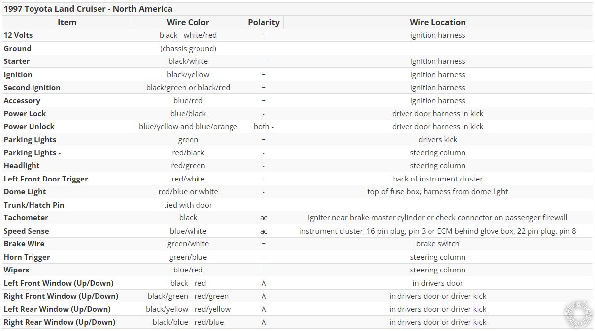
Working on a 1997 Land Cruiser - Viper 5706V Alarm/Remote Start. RS3000 was removed (OEM Security System). I have located all driver footwell harnesses & ignition harness. I have the EWD, and mixed results from many online forums & posts (there were variances in what goes where). Voltage status tested on the ignition harness w/ key position: CONSTANT, ACC, ON, START
11-PIN Ignition Harness has the following colors:
Male Plug End ; Female Socket End:
1 B-W ; B-W : START
2 B-Y ; B-Y : ON
3 L-R ; L-R : ACC & ON
4 B-R ; B : CONSTANT
5 Br-R ; Empty
6 Br-W ; B-R : ON
7 L ; W-B
8 L ; G-B
9 G-W ; W-B
10 G-W ; R-B
11 Br ; W-R : CONSTANT
I need to determine what to connect / where to connect the Viper wires.
MAIN 6-PIN
1 R 12V (+) CONSTANT
DONE
2 B GROUND (-)
DONE
3 Br SIREN OUTPUT (+)
DONE
4 W-Br PARKING LIGHT ISOLATION #87A N/C ONBOARD RELAY
5 W PARKING LIGHT OUTPUT #30 COMMON ONBOARD RELAY
6 O GWA (-) GROUND WHEN ARMED OUTPUT
DOOR LOCK 3-PIN FRONT TWO DOORS WORKING, NEED TO DETERMINE REARS
1 L UNLOCK OUTPUT (-)
CONNECTED TO DRIVER DOOR KICK PANEL L-Y
2 EMPTY NOT USED
3 G LOCK OUTPUT (-)
CONNECTED TO DRIVER DOOR KICK PANEL L-B
REMOTE START 10-PIN NOT WORKING YET
1 EMPTY NOT USED
2 R-B FUSED 12V (+) ACCESSORY/STARTER INPUT
3 P-B FLEX (+) RELAY INPUT #87A N/C* KEY SIDE OF FLEX RELAY (IF R'QD)
4 P-W IGNITION (+) 2 / - #30 COMMON OF FLEX RELAY
5 R FUSED 12V (+) IGNITION 1 INPUT
CONNECTED TO IGNITION B-Y
6 G STARTER (+) INPUT KEY SIDE OF FAILSAFE STARTER DISABLE
CONNECTED TO IGNITION B-W
7 V STARTER (+) OUTPUT CAR SIDE OF FAILSAFE STARTER DISABLE
CONNECTED TO IGNITION B
8 O (+) ACCESSORY OUTPUT
DONE
9 R-W FUSED (+) 12V INPUT IGNITION 2 - #87 N/O* FLEX RELAY INPUT
10 P IGNITION (+) 1 INPUT/OUTPUT
AUX SHUTDOWN TRIGGER 24-PIN
1 P-W IGNITION 2 (-) FLEX RELAY OUTPUT
2 L-W 2ND STATUS REAR DEFOGGER OUTPUT (-)
3 R-W TRUNK RELEASE OUTPUT (-)
4 B-Y DOME LIGHT OUTPUT (-)
5 Drk L STATUS OUTPUT (-)
6 W-B AUX 3 OUTPUT (-)
7 W-V AUX 1 OUTPUT (-)
8 O-B AUX 4 OUTPUT (-)
9 Gr HOOD PIN INPUT (-) N/C OR N/O
CONNECTED TO HOOD PIN
10 L-W TRUNK PIN INSTANT TRIGGER INPUT (-) N/C OR N/O
11 W-L ACTIVATION INPUT
12 V-W* TACHOMETER INPUT
13 B-W** PARKING BRAKE (-) INPUT
GROUNDED THIS WIRE
14 G-B FACTORY ALARM DISARM OUTPUT (-)
15 G* DOOR INPUT (-)
16 Br-B HORN HONK OUTPUT (-)
NOT USING
17 P IGNITION 1 OUTPUT (-)
18 V* DOOR INPUT (+)
19 V-B AUX 2 OUTPUT (-)
20 Br BRAKE SHUTDOWN INPUT (+)
CONNECTED TO BRAKE SWITCH ABOVE PEDAL
21 V-Y STARTER OUTPUT (-)
22 Gr-B DIESEL WAIT TO START INPUT (-)
NOT USED
23 O ACCESSORY OUTPUT (-)
24 G-W FACTORY ALARM ARM OUTPUT (-)
* REQUIRED FOR MANUAL TRANS
** CONNECT TO PARK (-) BRAKE SWITCH


 Printable version


