the12volt.com spacer
icon

Subaru WRX multiple buttons project


Post ReplyPost New Topic
< Prev Topic Next Topic >
unclephil 
Member - Posts: 6
Member spacespace
Joined: May 23, 2003
Posted: July 07, 2003 at 9:36 PM / IP Logged  

Hi all.  I have a project for my wrx.  I'm a mechanical engineer, familiar a bit with eletric/electronics, but i do need your help.

Alot of people add electrical things to their car that require a switch to activate.  This project is about just that.  I will in the near future add lights and gadgets to the car that i will want to be able to turn off and on from a ''center console''.  What i would like to do is use the original pop-out cupholder (modified of course) to put a series of (lighted or not, preferably lighted) ) temporary push buttons ( 6 - 8 of em).  (u know what i mean by temporary ?) 

I want this to be verry neat, so i tought of using a standart connector in the back of the cupholder (in dash) to have a quick connect of these buttons.  I tought of using something like a printer cable connector ( u know, like 20 pins / holes in there) and make a circuit board to be able to hook all the buttons on the adaptor.

Then these would run threw a fuse control panel, under the dash and then to the motor compartment where i would have like a block full of relays to activate the gadgets (power the 12 volts).

I would like to hear your toughts about this project, and any suggestions u might think of ...

Like what kind of relay turns on with a temporary current and off if i press the button again ... ?  Also how would it work if i wanted the push button side of the circuit to run on low voltage (a transfo i guess ?) or could the small pins of the ''printer connector'' take the current good ? Would'nt it be too small for 12 volts ... even if its a temporary (momentry) signal ?

Another thing is, how small can these push buttons be ? The cup holder maybe like 1/2 - 5/8 in thick ... do u see what i mean ?

Are my explanations too wild ? Am I makin any sense at all ?!! héhé

Thanks in advance

Phil

auex 
Platinum - Posts: 5,041
Platinum spaceThis member has made a donation to the12volt.com. Click here for more info.spacespace
Joined: December 23, 2002
Location: Arizona, United States
Posted: July 07, 2003 at 10:00 PM / IP Logged  
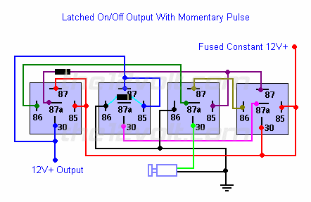
Well, my recommendation would be to look for some sort of pre-built control unit. As far as using something like printer cable, it may have the capacity to activate a relay but will not have the capacity to light the switch. Just to give you an idea of what you are up against, you will need one of the these( see diagram below) for each switch in order to turn the device on and off with a single switch.
Subaru WRX multiple buttons project -- posted image.
Certified Security Specialist
Always check info with a digital multimeter.
I promise to be good.
Tell Darwin I sent you.
I've been sick lately, sorry I won't be on much.
unclephil 
Member - Posts: 6
Member spacespace
Joined: May 23, 2003
Posted: July 08, 2003 at 9:02 AM / IP Logged  

Do you think it would be dangerous (small wires getting too hot) to use like a printer cable adaptor to activate the primary relay (3 rd one from left)?

And how would the lighting of the push button work ? I'm guessing its fed directly, and turns on and of (normaly off) when u push on it and turns off again when u turn the car off ?

Thanks

Phil

Big Purds 
Silver - Posts: 574
Silver spacespace
Joined: November 25, 2002
Location: Canada
Posted: July 20, 2003 at 4:13 AM / IP Logged  
as auex stated, the printer cable would probably not be able to carry enough current to light the switch...the switched take power from the connection they activate, and that small strand will not carry enough current...
like he said, it may carry enough current to signal the relay, but if you wanted lighted switches you would need a heavier cable...how many switches are you looking at using? you might be able to get away with a negative trigger (reversing polarity) setup so u can just ground one side of each switch close by and cut out half of the number of wires you would need to run to your relay packs...but only if you could get away without lighted switches...
but in any event a printer cable would probably be a bad idea...just look for some 22ga and some split loom...22ga is a very small wire itself, but will carry enough current to power a lighted switch...
xetmes 
Silver - Posts: 586
Silver spacespace
Joined: May 18, 2003
Posted: July 20, 2003 at 9:16 AM / IP Logged  

Here is what i would do:

Subaru WRX multiple buttons project -- posted image.

But thats because i like using electronics. It is based around a JK flip flop, with J and K tied making it a Toggle Flip flop. It drives a transistor, that in turn drives a standard 12 Volt relay. Also i put in an LED for visual feedback, if you are using lighted switches, you could use that power. I think it would look better though if you put just a standard momentary switch with an LED above it, but thats just me. That chip it is based around (4027) is about $0.50 and has 2 flip flops in it so its not an expensive projest or anything. Well thats my idea. Good luck with the project. Subaru WRX multiple buttons project -- posted image.


Sorry, you can NOT post a reply.
This topic is closed.

  Printable version Printable version Post ReplyPost New Topic
You cannot post new topics in this forum
You cannot reply to topics in this forum
You cannot delete your posts in this forum
You cannot edit your posts in this forum
You cannot create polls in this forum
You cannot vote in polls in this forum

  •  
Search the12volt.com
Follow the12volt.com Follow the12volt.com on Facebook
Thursday, May 16, 2024 • Copyright © 1999-2024 the12volt.com, All Rights Reserved Privacy Policy & Use of Cookies
Disclaimer: *All information on this site ( the12volt.com ) is provided "as is" without any warranty of any kind, either expressed or implied, including but not limited to fitness for a particular use. Any user assumes the entire risk as to the accuracy and use of this information. Please verify all wire colors and diagrams before applying any information.

Secured by Sectigo
the12volt.com spacer
Support the12volt.com
Top
the12volt.com spacer