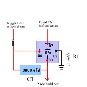
ok, never having heard of door locks that work on anything other than 12volts, you've got me there. what i would do if i were you, since the alarm output is max at 200 milliamps, you need to get yourself a pair of bosch relays that are used to switch the door locks from the battery (fuse them of course) -- you will blow your alarm eventually if not. now, as far as getting the two second pulse, you can try doing a couple of different ways. i'll make a pic to explain - you'll have to experiment with the value of the capacitor - the higher value you go, the longer the pulse will last ..... but it will not be working like what most people will think - this capacitor is holding the relay down while the cap is charging, not while it's discharging. i'll also tie a bleed resistor on the circuit, so that if you want to lock/unlock quickly, you wont have to wait for the capacitor to discharge on it's own for the following cycle.

ok, you'll have to experiment with the value of c1. R1 should be somewhat high to start off with, otherwise, as soon as the capacitor charges, the relay will shut off, then the bleed resistor will bleed the load of the cap across the coil of the relay, turning it back on again. the idea is to get the resistance just high enough that the relay wont be able to activate while bleeding the power off the cap when it shuts off. here's how this circuit works: the moment power initially comes in from the alarm and activates the relay, it also ensures that the potential across the capacitor is equal (cap discharged). the moment that power is removed from the alarm, the power begins to flow thru the cap to charge it. that current is sufficient to keep the relay closed. the higher value capacitor, the longer it will take to charge, so the longer it will hold the relay down. once the cap is charged, it will no longer allow current to pass, and the relay will shut down. when that happens, the potential stored in the capacitor is bled off on R1. probably start R1 off somewhere around 500 ohms and go up or down from there to see how well it works for you. this particular circuit can be added to many circuits, and altered sufficiently to provide as much delay as needed - i've adjusted it to give over 20, 30 seconds before depending on what it's used for. this is just a single pulse circuit - you may need to have two (one for lock, one for unlock) - or up, down, etc. if you have problems, leave a followup here, and i'll track down more precise values and more specific components for you.
 Printable version


