Here you go this should help you out, use S.P.D.T Relays 30AMP (Single Pole Double Throw) These are standerd automotve relays. You will Also need 1amp Diodes id you are hooking up door triggers.
If you need any thing else let me know.
| ITEM | WIRE COLOR |POL| WIRE LOCATION |
| 12V | red |+ | ignition harness |
| STARTER| yellow |+ | ignition harness |
| IGNITION| pink |+ | ignition harness |
| SECOND IGNITION| blue |+ | ignition harness |
| ACCESSORY|orange |+ |ignition harness |
| POWER LOCK|lt. blue |+ |gray conn R of e-brake *3 |
| POWER UNLOCK|white |+ |gray conn R of e-brake *3 |
| PARKING LIGHTS +|brown | |steering column |
| HEADLIGHTS|tan(low) green(hi) |+ |steering column |
| DOOR TRIGGER|*2 |- |*2 |
| TRUNK/HATCH PIN| | | |
|TRNK/HTCH RELEASE|black |+ |at keyless module *4 |
| TACHOMETER|PURPLE / white | |ECM *1 |
| BRAKE WIRE|lt. blue |+ |brake switch |
| HORN TRIGGER| black | - | stering column |
| WIPERS| | | |
| LF WINDOW UP/DN|blue - brown |A |center console |
| RF WINDOW UP/DN|lt. blue - tan |A |center console |
| LR WINDOW UP/DN| | | |
| RR WINDOW UP/DN| | | |
Notes:
*1 The ECM is located in the passenger footwell, and you can find the PURPLE / white in the large connector exiting to the right of the ECM. *2 The driver door trigger wire is lt. GREEN/ black and the rear door trigger wire is yellow, both in the driver kick panel. The passenger door is lt. blue in the passenger kick panel. Use all wires and diode isolate. *3 Also found at door lock relays, drivers underdash left of steering column. *4 The keyless module is located in the trunk on the drivers side. There is no power trunk release on models not equipped with keyless-entry module.
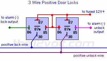
This is one of the most common type of door lock switch configurations found in most vehicles. In most cases you will not need to add relays for this type. Most of the newer alarms and keyless entries on the market today have both positive and negative 200 ma door lock outputs that are usually capable of activating the factory relays. Should you need to add relays for a "3 wire negative" door lock system, just change both normally open terminals (87) from 12V(+) to ground. If your alarm or keyless entry has positive outputs only, you will have to connect the other side of the coils to ground and connect your outputs as shown. The lock and unlock wires below refer to the switch leads, not the motor legs.
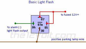
If the alarm or keyless entry you are installing has a light flash output other than one (with an on board relay) that is connected directly to the parking lamps. The connections are shown below. If you need to connect to a left and right parking lamp circuit, see next. If your alarm has no light flash output, click here.


 Door Triggers / Pin Switches Door Triggers / Pin Switches |
| Door Triggers |
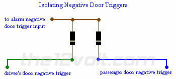
Pin switches rarely need to be added to protect the doors of a vehicle. But when they do, try installing a factory switch instead of an aftermarket one on the vehicles that have a preexisting hole. The time saved is usually worth the added cost of the switch. On some vehicles, tying into the door triggers is as simple as connecting to the lead of the dome lamp that changes from (+) 12 VDC to ground, or vice-versa on Fords, when any door is opened. However, some vehicles have a dome lamp delay and/or an auto off feature. On many of these, you will want to locate the trigger lead(s) that will show either ground or (+) 12VDC when each door is opened, that is not affected by the dome lamp being on or off. On the vehicles that have two separate (-) door triggers that are isolated from each other, most commonly found on newer GM vehicles, you will need to use two 1 amp blocking diodes for all doors to trigger the alarm.. One trigger is for the driver's door and the second is for the rest of the doors. If you were just to connect to one of these and not both, one or more doors of the vehicle would not be protected by the alarm. If you were to tie each of these together without the blocking diodes, some features of the vehicle will no longer function properly. Below is an example of connecting them to one alarm trigger. If you need to isolate two (+) positive door triggers, simply reverse the position of the blocking diodes, facing the anode sides towards the door triggers and the cathode sides towards the alarm. This diagram would also apply to connecting the (-) outputs of two sensors, such as a glass mic and an impact sensor, to one input of an alarm. |
The Shagmaster
1999 Chevy Suburban 15" lift sittn on 22's sets 7'5"
1992 Chevy Astro Van all Bagged out Dubbed THE SUICIDER
Installing for over 18 years Looking for empolyment NOW send PM for resum
 Printable version


