the12volt.com spacer
icon

Kind of a complicated circuit..see inside


Post ReplyPost New Topic
< Prev Topic Next Topic >
hbidad 
Member - Posts: 6
Member spacespace
Joined: February 20, 2004
Location: United States
Posted: February 20, 2004 at 5:20 PM / IP Logged  

Ok, just let me tell you that this is another one of those Turn signal/Brake light intergration. However, after reading this whole relay forum, I still have not found the write diagram for my project. Let me explain my situation .

I am dealing with an 03 yamaha R6 with led tail lights. Everything is wored up into 1 circuit (only 1 Stop, tail and ground). I am planning on trying to make my own PCB board and convert the single circuit into 2 seprate ones so I could have use one side as turn signals. I have made plenty of DIY boards and projects, but I always used a "HOW-TO" guide.  I know I am capable of doing this. I also know that there is a few retail kits that  replace the whole tailight to intergrate everything. However, I am tired of the how to's and I am ready to learn.

Anyhoo, I keep hearing about using gates. This all confuses me. If that would be the easiest way,  can you guys explain (in noobie language)? On the other hand, if using relays would be better, could you help me get this going? Details below...

My tail light is always on (parking lights) and of course they get bright when I hit the brakes.

What I need is something that would allow one side to blink but allow the parking light to remain on during the whole blink sequence.

Basicly it goes like this...  dim....bright...dim...bright.

However, I would need this sequence when the brake is on also.

Any comments sugestions?

xetmes 
Silver - Posts: 586
Silver spacespace
Joined: May 18, 2003
Posted: February 21, 2004 at 7:03 AM / IP Logged  

If you are willing to do this I probably wont be too bad. I am kind of confused though, how many different states are there? Try to make a chart so you know exatly what you want.

Like:

__________Parking light_____Brake light____etc....

inner LED    |    ON                 |              ON

outer LED    |     OFF              |              ON

then it will be much easier to determine the logic needed. You can always use logic (AND,NAND,OR,NOR,XOR....) or you can use a microcontroller, but a microcontroller requires a programmer. Honestly there is only so many things that can be done with realys, you could probably do this with relays but you may need a giant bank of them.

Gates are just semiconductor logic, performs specific switching without moving parts.

Again I am not all that sure what you want so I would recommend making up a table.

hbidad 
Member - Posts: 6
Member spacespace
Joined: February 20, 2004
Location: United States
Posted: February 21, 2004 at 9:26 AM / IP Logged  

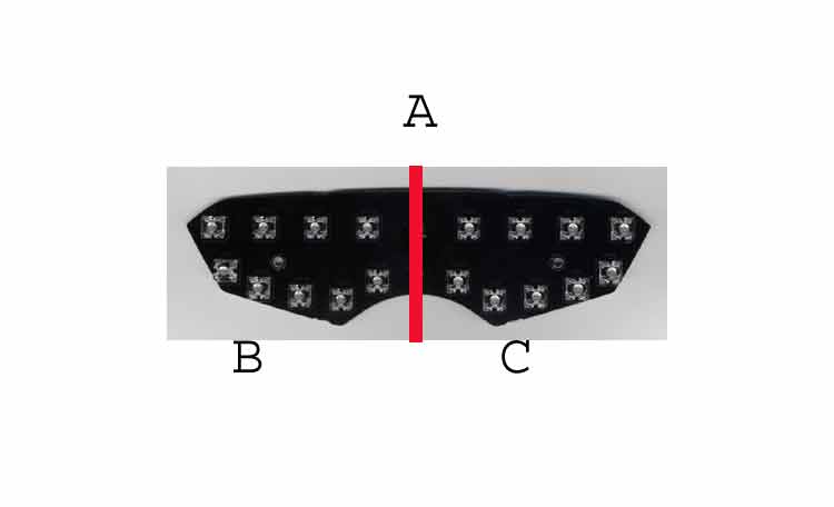
Hi, thanks for the replay! To help explain things, I will show you some pictures of my tail light/

Kind of a complicated circuit..see inside -- posted image. 

The Leds are wired with a series of resistors to allow the running light to be dim in a normail stage.  When the brake is applied, it activates another circuit wired with less resistors to  make the leds brighter.

My attempt at the table would be something like this: (I am going to use B as the left turn signal.)

                __________  Parking light  |  Brake light  |  Turn/Flash

running/Parking             |    B/C ON     |   B/C OFF     |        OFF               

Left turn                           |     B/C On     |          Off        |      B On                  

Left Turn while braking  |     B/C ON     |         C on     |      B on

And Vice versa for right hand turns.  Since the running light will always be on I guess the only problem to needs to be worked on is to have the ability to flash the turn signal (bright -dim) while the brake is being applied.

xetmes 
Silver - Posts: 586
Silver spacespace
Joined: May 18, 2003
Posted: February 21, 2004 at 11:37 AM / IP Logged  

Im still a little confused, are you going to build a new board and new LEDs to make a complete replacement for the entire light assembly? What I get out of this is that the entire light only has 3 settings: off, low and high...?  If you are going to make a new assembly are you going to reuse the LEDs? Is the lens red? if not or if the lens is not that dark of a red it might be possible to add amber leds.... Just trying to fully understand before i say anything..

hbidad 
Member - Posts: 6
Member spacespace
Joined: February 20, 2004
Location: United States
Posted: February 21, 2004 at 12:21 PM / IP Logged  

hi, Yes I am going to redo the PCB and use the same leds. They are really bright. Amber leds? Yeah, I have really been thinking about that also. That kinda sounds a little easier. If you could, help me go that way.

On the board there is 3 solder pads... Ground, tail and stop. what about this...

Take a look at  this. This is what my tail light looks like. This is what I was trying to explain above with the exeption that when the turn signal is on, and instead of going from bright to off, it would go bright to dim.

http://www.flashalert.com/flash/integrator2.swf

sorry for the confussion. I am not very good at explaining things

xetmes 
Silver - Posts: 586
Silver spacespace
Joined: May 18, 2003
Posted: February 22, 2004 at 10:29 AM / IP Logged  

ohh that animation clears it up.

with a microcontroller that would be easy, with normal logic it will be a little more difficult.

I am assuming the feed wire from the turnsignals that you plan on using are after the flasher and will pulse on and off?

yea if i had that clear lens like that i would put amber and red leds in just for the hell of it, why not go all out.

i think the problem really lies in all the different states, the fact that the brake light flashes will mean you will need another flasher circuit so that without a turnsignal wire it will still operate...

How much electronics experience do you have, you say you have made boards before...?

with a microcontroller based project you are looking at 1 chip, a voltage regulator, some transistors, some resistors and a few caps... with logic it will probably be a good amount more...

hbidad 
Member - Posts: 6
Member spacespace
Joined: February 20, 2004
Location: United States
Posted: February 22, 2004 at 12:11 PM / IP Logged  
Hi, my knowledge on how to design circuit is at the min. All my projects that I have done where very well documented and was no problem for a newbie like me. Since I have no clue how to program, I guess I have to stick to the logic. Would you think the mebers here would be willing to do a side job to design this?
superchuckles 
Copper - Posts: 89
Copper spacespace
Joined: December 29, 2003
Location: United States
Posted: February 23, 2004 at 3:40 AM / IP Logged  
the actual job is easier than you think - all you really need to do is, seperate the turn/brake signals where they're consolidated (usually within the turn signal switch inside the steering column).  all you really need to do if you want to make your turn signals seperate from your brake lights (so you have different actual lights for each) is to cut the existing brake light power circuit before it goes into the turn signal switch, and run it from that point, to the new brake lights in the back.  you would run your existing lights for turn signals.  for the tail lights part, just move the tail light wire over to the brake lights side, so they go dim/bright for tail/brake lights, and your existing wire runs the turn signals.  no circuit boards would need to be aded unless your adding some kind of sequencing lights that flash from the inside out or something (which is easy enuf to do too).  if you really need help with this,  and you've got a schematic of your car's wiring, or know how to use a test light and just need some help with it, email me and i'll walk ya thru doing it.  email at savage_american@hotmail.com  and put the word WIRING in the subject so i don't just delete it with the usual junk email.
xetmes 
Silver - Posts: 586
Silver spacespace
Joined: May 18, 2003
Posted: February 23, 2004 at 6:28 AM / IP Logged  
The problem is that if you just hook up the brake light and the turn signal, any time you use the brake with the turn signal on you will not see the flashing turn indicator, you need to disable one side of the brake light when the turn signal is on if I understand corectly. Also to make the brake light flash when the turn signals are off is going to require a clock generator I would assume since normally the brake light is a constant signal.
white caddy 
Member - Posts: 28
Member spacespace
Joined: January 26, 2004
Location: United States
Posted: March 18, 2004 at 11:51 PM / IP Logged  
hbidad,
do you know they sell a set-up just like the one you want to make? i was going to buy if for my 93 gsxr. it doesnt have led tail lights but it has two brake lights.
i think i saw it on ebay or a dennis kirk catalog.
d.s.
Page of 2

  Printable version Printable version Post ReplyPost New Topic
You cannot post new topics in this forum
You cannot reply to topics in this forum
You cannot delete your posts in this forum
You cannot edit your posts in this forum
You cannot create polls in this forum
You cannot vote in polls in this forum

  •  
Search the12volt.com
Follow the12volt.com Follow the12volt.com on Facebook
Friday, March 29, 2024 • Copyright © 1999-2024 the12volt.com, All Rights Reserved Privacy Policy & Use of Cookies
Disclaimer: *All information on this site ( the12volt.com ) is provided "as is" without any warranty of any kind, either expressed or implied, including but not limited to fitness for a particular use. Any user assumes the entire risk as to the accuracy and use of this information. Please verify all wire colors and diagrams before applying any information.

Secured by Sectigo
the12volt.com spacer
Support the12volt.com
Top
the12volt.com spacer