the12volt.com spacer
icon

Help Please: DirectStart CS 423


Post ReplyPost New Topic
< Prev Topic Next Topic >
Congo 
Member - Posts: 9
Member spacespace
Joined: August 17, 2002
Location: Canada
Posted: August 25, 2002 at 7:08 PM / IP Logged  

Hi,

I've installed the CS 423 on my Hyundai Sante Fe. I can start it, stop it, lock it, unlock it. I can chirp the horn on lock and unlock.

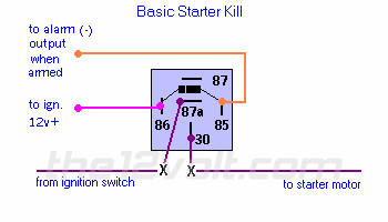
I want to incorporate the starter kill listed below. I know that the orange wire (in picture) would go to pin 6 (brown wire) on the 14 pin conn. of the starter module.

I'm not sure about the other wires. In the pic below, the fuscia wire goes "to ign. 12v+". What do I do with the blue wire from pin #5 on J1 (starter module)? Then, if I cut the ign. switch to start solinoid wire on my ign. switch and attach to the relay, what do I do with the yellow wire from pin #3 on J1 (starter module)?

Help Please: DirectStart CS 423 -- posted image.

Next Questions:

1. What do they mean by active versus passive door locking when programming Bank 1?

2. I've enabled the alarm setting (Bank 1, function 8, option 2). I've connected the WHITE/ violet wire to my door pin switch (J2 -Pin #3). This switch sees 0 volts when the door is open and 12 volts when the door is closed. The external trigger setting in programming is default so that should work. The question is: How do I test to see if the alarm function works. I tried unlock the door manually and opening the door but that didn't work.

3. Does this unit support the auto locking of doors while driving then unlocking when I shut the car off?

Thanks for the time.

Velocity Motors 
Moderator - Posts: 12,488
Moderator spaceThis member has made a donation to the12volt.com. Click here for more info.spaceThis member has been recognized as an authority in Electrical Theory. Click here for more info.spaceThis member has been recognized as an authority in Fabrication. Click here for more info.spaceThis member has been recognized as an authority in Mobile Audio and Video. Click here for more info.spaceThis member has been recognized as an authority in Mobile Security and Convenience. Click here for more info.spacespace
Joined: March 08, 2002
Location: Manitoba, Canada
Posted: August 25, 2002 at 10:43 PM / IP Logged  

Yes the BROWN wire is correct as well as the BLUE wire on J1 for the primary ignition. What you have to do is to cut the STARTER wire from the ignition harness in half so you have a motor side and a switch side. Wire the switch side to the starter wire to 87a and then take the other half of the starter wire and atach it to 30 of the relay. Now take the YELLOW wire from J1 and attach it to MOTOR side of the starter wire.

  • 1. Active means you control the lock and unlock while passive means auto lock/unlock
  • 2. Manually ground the target wire to see if the module is defective or not. 99 % of the time though it's programming error. Just make sure that you have the programming right.
  • 3. Yes it does. BANK 1 .....FUNCTION 5..... OPTION 2 will allow for ignition controlled door lock and unlock.

Hope this helps and good luck... these are great systems just the programming is a little confusing.

Jeff
Velocity Custom Home Theater
Mobile Audio/Video Specialist
Morden, Manitoba CANADA
Congo 
Member - Posts: 9
Member spacespace
Joined: August 17, 2002
Location: Canada
Posted: August 26, 2002 at 4:35 AM / IP Logged  

Thanks for the much need explanation of the final connections Jeff.

So that I understand correctly...

1. The blue wire (pin #5, J1) continues to go to the ignition switch TOGETHER with the fuscia wire in the pic.

2. When I cut the starter wire (mine is quite small, maybe 16 or 18 guage, is that normal?) I attach the switch side to terminal 87a on the relay and I attach the starter motor side to terminal 30 on the relay. I also attach the yellow wire (pin #3, J1) to terminal 30 on the relay as well.

If I program for passive lock/unlock, when do they automatically lock/unlock? Does it work in combination with the ignition lock unlock in Bank 1, function 5? Currently I am using passive.

Thanks again for the help,

Greg

Velocity Motors 
Moderator - Posts: 12,488
Moderator spaceThis member has made a donation to the12volt.com. Click here for more info.spaceThis member has been recognized as an authority in Electrical Theory. Click here for more info.spaceThis member has been recognized as an authority in Fabrication. Click here for more info.spaceThis member has been recognized as an authority in Mobile Audio and Video. Click here for more info.spaceThis member has been recognized as an authority in Mobile Security and Convenience. Click here for more info.spacespace
Joined: March 08, 2002
Location: Manitoba, Canada
Posted: August 26, 2002 at 7:23 AM / IP Logged  

1. The blue wire (pin #5, J1) continues to go to the ignition switch TOGETHER with the fuscia wire in the pic.

  • Yes this is correct

2. When I cut the starter wire (mine is quite small, maybe 16 or 18 guage, is that normal?) I attach the switch side to terminal 87a on the relay and I attach the starter motor side to terminal 30 on the relay. I also attach the yellow wire (pin #3, J1) to terminal 30 on the relay as well.

  • The gauage wire doesn't mean anything , just make sure that you test that the target wire has the characteristics that you arse looking for . The starter wire should only have 12 volts power in the start postion and 0 voltage in all other positions of the key. The connections above are correct as well.

If I program for passive lock/unlock, when do they automatically lock/unlock? Does it work in combination with the ignition lock unlock in Bank 1, function 5? Currently I am using passive.

  • You can program the passive lock/unlock for 30 sec or 60 sec. after ignition is turned off. You have to have BANK 1....FUNCTION 1...& press button # 2 in order to use the passive lock and then you have to program BANK 1....FUNCTION 2 for either OPTION 1 ( 30 seconds ) or OPTION 2 ( 60 seconds ).
Jeff
Velocity Custom Home Theater
Mobile Audio/Video Specialist
Morden, Manitoba CANADA
Congo 
Member - Posts: 9
Member spacespace
Joined: August 17, 2002
Location: Canada
Posted: August 26, 2002 at 5:29 PM / IP Logged  

Thanks for the answers Jeff. I will try the starter disable again on the weekend. So it appears that even though I have selected passive locking in function 1, it won't work until I select passive arming in function 2.

I understand that dealers normally install these units but with a few extra instructions, the technically capable do-it-yourselfer would also be able to install these units a little easier. I had all the basic wiring figured out within an hour. Most of my time was spent soldering and doing a neat wiring job complete with documentation for future reference.

Thanks again for your help. I let you know how it works out for me.Help Please: DirectStart CS 423 -- posted image.


Sorry, you can NOT post a reply.
This topic is closed.

  Printable version Printable version Post ReplyPost New Topic
You cannot post new topics in this forum
You cannot reply to topics in this forum
You cannot delete your posts in this forum
You cannot edit your posts in this forum
You cannot create polls in this forum
You cannot vote in polls in this forum

  •  
Search the12volt.com
Follow the12volt.com Follow the12volt.com on Facebook
Monday, August 18, 2025 • Copyright © 1999-2025 the12volt.com, All Rights Reserved Privacy Policy & Use of Cookies
Disclaimer: *All information on this site ( the12volt.com ) is provided "as is" without any warranty of any kind, either expressed or implied, including but not limited to fitness for a particular use. Any user assumes the entire risk as to the accuracy and use of this information. Please verify all wire colors and diagrams before applying any information.

Secured by Sectigo
the12volt.com spacer
Support the12volt.com
Top
the12volt.com spacer