the12volt.com spacer
icon

Viper ESP550 Trunk Output


Post ReplyPost New Topic
< Prev Topic Next Topic >
fierygt 
Member - Posts: 22
Member spacespace
Joined: September 19, 2004
Location: United States
Posted: September 20, 2004 at 11:10 PM / IP Logged  

Viper ESP550 Trunk Output - Page 2 -- posted image.

fierygt 
Member - Posts: 22
Member spacespace
Joined: September 19, 2004
Location: United States
Posted: September 20, 2004 at 11:17 PM / IP Logged  
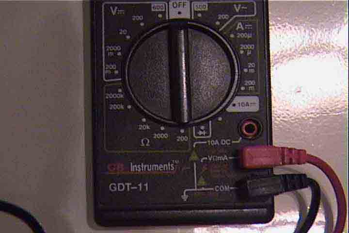
ok teken, i figured i would just show you the multimeter i am using.  when i tested, i turned the dial to both the 20m and the 200m, which are on the right side of the unit.(if the picture is bad) That is where i got my 1.3 and 1.30 readings. And the probes are set up exactly as the picture shows.  Thanks for the constant help.
Teken 
Gold - Posts: 1,492
Gold spacespace
Joined: August 04, 2002
Location: Aruba
Posted: September 21, 2004 at 8:31 AM / IP Logged  
Interesting, I have not seen a meter use both volts and amps in the same out let before.
GB is a good brand anyways, no worries.
When you set the meter to 200 mA, did the meter show you any reading?
Remember you must place the meter inline (series) with the circuit to measure the current (I).
Just want to make sure this is being done.
If you have to set it to 20 mA to obtain a reading, then yes the output is dead.
Follow up with a voltage measurement as well, and let us know what the voltage is coming out of the unit, when you depress the key fob.
Regards
EVIL Teken . . .
fierygt 
Member - Posts: 22
Member spacespace
Joined: September 19, 2004
Location: United States
Posted: September 21, 2004 at 11:35 AM / IP Logged  
Teken forgive me, but not sure what you mean when you say "Remember you must place the meter inline (series) with the circuit to measure the current (I). "
Teken 
Gold - Posts: 1,492
Gold spacespace
Joined: August 04, 2002
Location: Aruba
Posted: September 21, 2004 at 4:23 PM / IP Logged  
When measuring voltage you are placing the meters leads in parallel to the point to be measured.
When current is being measured, you must break the circuit which is under test. And place the DMM leads in series with the circuit.
ie. Alarm CPU outout ---> Neg (-) DMM cable ---> Pos (+) DMM cable to the relay in question.
One side of the DMM will be attached to the output of the alarm trunk output wire, the other end of the DMM lead will attach to the other wire leading to the relay.
Hope that clarify it for you, if not, I will try to rephrase it for you.
Regards
EVIL Teken . . .
fierygt 
Member - Posts: 22
Member spacespace
Joined: September 19, 2004
Location: United States
Posted: September 21, 2004 at 4:55 PM / IP Logged  

Hey Teken, I got what you mean now.  Anyway here are the readings...

If multimeter is set to 20mA, I get reading of 1.25

If multimeter is set to 200mA, I get reading of 01.3

Now, on the voltage side, if i set multimeter to 20Volts, I get reading of 0.60

If multimeter is set to 2000m, on voltage side, i get reading of 587...

Now here's an interesting one which i'm not sure of...On the right side of the multimeter, where the ampere settings are, there is one called 2000u, which the reading on that one is 1190.  So can you help me translate these numbers and tell me what might be next?  Thanks Again

mito57 
Member - Posts: 46
Member spacespace
Joined: April 21, 2004
Location: United States
Posted: September 21, 2004 at 5:25 PM / IP Logged  
The "u" is really the greek letter for "m" and stands for "micro". So if your range is 2000 u that means a full scale of 2,000 divided 1,000,000. That is a maximum reading of .001190 Amp if you are reading 1190, which is equivalent to a reading of 1.19 in the 20mA scale. 
kgerry 
Platinum - Posts: 3,455
Platinum spaceThis member consistently provides reliable informationspace
Joined: February 07, 2004
Location: Saskatchewan, Canada
Posted: September 21, 2004 at 6:44 PM / IP Logged  
the aux channel is smoked...... you can replace the transsitor inside or ship it in to be serviced....
Kevin Gerry
Certified Electronics Technician
MECP First Class Installer
Owner/Installer
Classic Car Audio
since 1979
fierygt 
Member - Posts: 22
Member spacespace
Joined: September 19, 2004
Location: United States
Posted: September 21, 2004 at 6:50 PM / IP Logged  

hey kgerry do you happen to know how to locate the correct transistor in the unit?  Thanks for the replies everyone.

fierygt 
Member - Posts: 22
Member spacespace
Joined: September 19, 2004
Location: United States
Posted: September 24, 2004 at 8:50 PM / IP Logged  
hey all. problem fixed!  Problem was a resistor located at the trunk output terminal.  Replaced with a 10ohm(What the unit calls for)and now it works perfectly!  Consider this topic closed.
Page of 3

  Printable version Printable version Post ReplyPost New Topic
You cannot post new topics in this forum
You cannot reply to topics in this forum
You cannot delete your posts in this forum
You cannot edit your posts in this forum
You cannot create polls in this forum
You cannot vote in polls in this forum

  •  
Search the12volt.com
Follow the12volt.com Follow the12volt.com on Facebook
Monday, May 6, 2024 • Copyright © 1999-2024 the12volt.com, All Rights Reserved Privacy Policy & Use of Cookies
Disclaimer: *All information on this site ( the12volt.com ) is provided "as is" without any warranty of any kind, either expressed or implied, including but not limited to fitness for a particular use. Any user assumes the entire risk as to the accuracy and use of this information. Please verify all wire colors and diagrams before applying any information.

Secured by Sectigo
the12volt.com spacer
Support the12volt.com
Top
the12volt.com spacer