the12volt.com spacer
icon

sentra 92 door locks


Post ReplyPost New Topic
< Prev Topic Next Topic >
mobiletoys2002 
Gold - Posts: 1,050
Gold spacespace
Joined: April 12, 2002
Location: United States
Posted: October 17, 2002 at 1:45 PM / IP Logged  
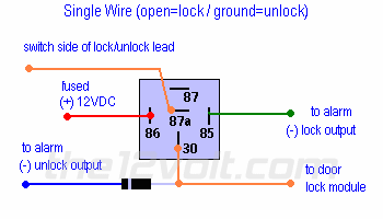
87a is the middle pin of a relay this pin is normally closed meaning always has continuity with pin 30 until voltage is aplied to the coil of the relay(pin85-86) when voltage is aplied the pins switch so that 87 and 30 have continuity but you wont connect anything on 87 therefore breaking the circuit and locking the doors. on unlock you are not breaking the wire you are giving it a (-)pulse to pin 87a to unlock do you understand now???
mobiletoys2002 
Gold - Posts: 1,050
Gold spacespace
Joined: April 12, 2002
Location: United States
Posted: October 17, 2002 at 1:56 PM / IP Logged  
On the '91-'95 300ZX and the '92-'95 240SX, locate the lock/unlock wire in the driver's kick panel or door jamb. When this lead is cut, or opened, the doors will lock. When this lead is grounded. the doors will unlock. If you have positive door lock outputs read next.
sentra 92 door locks - Page 2 -- posted image.
mobiletoys2002 
Gold - Posts: 1,050
Gold spacespace
Joined: April 12, 2002
Location: United States
Posted: October 17, 2002 at 1:59 PM / IP Logged  
do you see pin 87 not conected that is the break on lock when pin 85 gets power it will cause th pins to change from 30-87a to 30 87 giving you th ebreak and then go back to pin 87a when the lock pulse is gone.when the unlock pulse is on 30 or 87a it will unlock your car.
sufferrar 
Copper - Posts: 190
Copper spacespace
Joined: July 17, 2002
Location: Trinidad and Tobago
Posted: October 18, 2002 at 5:36 AM / IP Logged  

I wired this up yesterday when i reached home . i found this exact circuit that you described in my installation guide from my alarm.

The circuit did'nt work.
The only way to get the door to close and stay closed is to break 30 from 87a and leave these points open .
I understand what you are saying and understand the circuit -
From the drawing i think that i have a mis conception of both the orange coloured wire in the drawing(switch side of the lock /unlock lead and the door lock module). i have only one wire which goes to the driver control panel that is it .  how do i determine from just one single wire -what goes on 87a and 30 .?

i have neg pulse outputs from the alarm. 

sufferrar 
Copper - Posts: 190
Copper spacespace
Joined: July 17, 2002
Location: Trinidad and Tobago
Posted: October 18, 2002 at 5:46 AM / IP Logged  

I wired this up yesterday when i reached home . i found this exact circuit that you described in my installation guide from my alarm.

The circuit did'nt work. The only way to get the door to close and stay closed is to break 30 from 87a and leave these points open .I appreciate all the help !!!

i know what the problem is now . from the relay diagram i must have both 87a and 30 wrong . all i have to work with is a single wire that goes to the driver control panel . that wire connects to ground for open . does this single wire go to 87a or 30 ? and if i just have one wire , where do the other wire come from ?

Ohmz 
Copper - Posts: 193
Copper spacespace
Joined: May 09, 2002
Location: United States
Posted: October 18, 2002 at 6:09 AM / IP Logged  

you have to cut the door lock /unlock wire. It's like a stater kill. Connect the side that locks the door to 30.

87a connects to the other end of your door lock.unlock wire.

after that, just follow the diagram. Let us know!

sufferrar 
Copper - Posts: 190
Copper spacespace
Joined: July 17, 2002
Location: Trinidad and Tobago
Posted: October 18, 2002 at 6:31 AM / IP Logged  

if the wire is cut one end goes to ground and the other goes to the control panel . what puzzles me is that one end is goes to ground if the doors are open. I think that i may have to find another wire at the control panel to tap off.

Ohmz 
Copper - Posts: 193
Copper spacespace
Joined: May 09, 2002
Location: United States
Posted: October 18, 2002 at 7:26 AM / IP Logged  

oh ok I just read your previuos posts. You need a constant ground to keep the locks on. You probably have the wrong wire. Keep on looking for the wires that are posted.

sufferrar 
Copper - Posts: 190
Copper spacespace
Joined: July 17, 2002
Location: Trinidad and Tobago
Posted: October 18, 2002 at 8:11 AM / IP Logged  

i think you have it back wards . i need a constant ground will keep the locks open. when the wire is open the locks will close .

but i agree that i may have the wrong wire.

originally my car had central locking where the driver door controlled the other doors . when you use the key on the outside of the door key hole it pushes a switch which controls the other 3 doors .i replaced the switch with an actuator at the driver door and wired parallel to the others so now i have 4 power locks in parallel. one of the wire from the switch goes to ground and the other to the control panel . this is the wire i'm using to control the doors . the switch just closes or opens to ground.

my car also has a speed sensor that locks all doors at 15km/h. i don't think that this will affect anything but i'm still mentioning it .

i can use the neg. armed output from the alarm to control this wire but i wouldn't have the ignition controlled locks.!! i'll have to keep looking ....

sufferrar 
Copper - Posts: 190
Copper spacespace
Joined: July 17, 2002
Location: Trinidad and Tobago
Posted: October 21, 2002 at 5:44 AM / IP Logged  

I looked yesterday- no other wire other than the green with black stripe . one wire system - ground for doors to open , when removed from ground the locks open.

 I even busted open the driver console panel  to see if there are any hidden wires. i traced each point of the factory unlock/lock switch but it goes to some nitty-gritty semiconductors.

where do i go from here ? all help appreciated...!!!!!

Page of 2

Sorry, you can NOT post a reply.
This topic is closed.

  Printable version Printable version Post ReplyPost New Topic
You cannot post new topics in this forum
You cannot reply to topics in this forum
You cannot delete your posts in this forum
You cannot edit your posts in this forum
You cannot create polls in this forum
You cannot vote in polls in this forum

  •  
Search the12volt.com
Follow the12volt.com Follow the12volt.com on Facebook
Saturday, May 11, 2024 • Copyright © 1999-2024 the12volt.com, All Rights Reserved Privacy Policy & Use of Cookies
Disclaimer: *All information on this site ( the12volt.com ) is provided "as is" without any warranty of any kind, either expressed or implied, including but not limited to fitness for a particular use. Any user assumes the entire risk as to the accuracy and use of this information. Please verify all wire colors and diagrams before applying any information.

Secured by Sectigo
the12volt.com spacer
Support the12volt.com
Top
the12volt.com spacer