Posted: December 30, 2004 at 7:57 PM / IP Logged
Posted: January 01, 2005 at 2:35 AM / IP Logged
Posted: January 01, 2005 at 11:46 AM / IP Logged
Sorry, you can NOT post a reply.
This topic is closed.
 Printable version


| You cannot post new topics in this forum You cannot reply to topics in this forum You cannot delete your posts in this forum You cannot edit your posts in this forum You cannot create polls in this forum You cannot vote in polls in this forum |

| Search the12volt.com |
Follow the12volt.com 
Wednesday, May 15, 2024 • Copyright © 1999-2024 the12volt.com, All Rights Reserved • Privacy Policy & Use of Cookies


Wednesday, May 15, 2024 • Copyright © 1999-2024 the12volt.com, All Rights Reserved • Privacy Policy & Use of Cookies
Disclaimer:
*All information on this site ( the12volt.com ) is provided "as is" without any warranty of any kind, either expressed or implied, including but not limited to fitness for a particular use. Any user assumes the entire risk as to the accuracy and use of this information. Please
verify all wire colors and diagrams before applying any information.


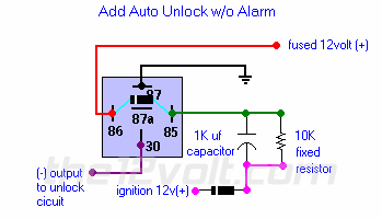
 I went and got a 1K uf capacitor and wired this circuit exactly as shown.
When it is hooked up like the diagram, the relay never clicks. When I take the ignition wire adn put it on the other side of the diode next to the capacitor and resistor, then it works to click and unlock when you turn your car off, but also when you turn your car on.
This is not good. I am not sure why this won't work with the diode in place, any help would be great!
I also put the diode across terminals 85 and 86, but nothing resulted or changed. I still don't understand what this does, I have managed to find something about when the relay closes, it handles a current spike, but I'm not sure what you're supposed to be protecting and which way it is supposed to protect.
I still need help with these if you could be kind enough to help me out some!
Thanks in advance!
Chris.