


2003 silverado power mirrors


Posted: February 14, 2005 at 12:35 AM / IP Logged


Posted: February 14, 2005 at 4:51 AM / IP Logged
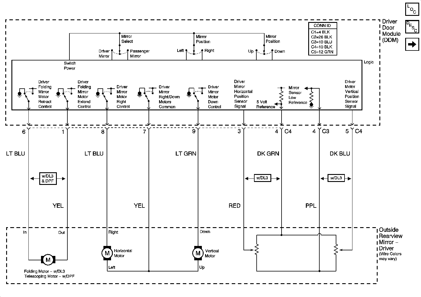
 Driver Door Module (DDM) - C3 - (Except Base)
Connector Part Information
6383393-7
10-Way F 0.64mm Unsealed AMP (BLU)
Pin
Wire Color
Circuit No.
Function
1
BRN/WHT
--
Left Turn Signal Low Reference
2
GRY/BLK
--
Left Turn Signal Control
3
BLK
--
Driver Mirror Heating Element Low Reference
4
PPL
--
Mirror Sensor Low Reference
5
--
--
Not Used
6
ORN/BLK
--
Left Door Exterior Courtesy Lamp Supply Voltage
7
GRY
--
Automatic Day/Night Mirror Signal
8
PNK
--
Automatic Day/Night Mirror Low Reference
9
BLK
--
Left Door Exterior Courtesy Lamp Ground
10
--
--
Not Used
Driver Door Module (DDM) - C4 - (Except Base)
Connector Part Information
6383393-5
10-Way F 0.64mm Unsealed AMP (BLK)
Pin
Wire Color
Circuit No.
Function
1
YEL
--
Driver Folding Mirror Motor Extend Control
2
ORN
--
Mirror Heating Element Supply Voltage
3
RED
--
Driver Mirror Horizontal Position Sensor Signal
4
DK GRN
--
5 Volt Reference
5
DK BLU
--
Driver Mirror Vertical Position Sensor Signal
6
LT BLU
--
Driver Folding Mirror Motor Retract Control
7
YEL
--
Driver Mirror Right/Down Motors Common
8
LT BLU
--
Driver Mirror Motor Right Control
9
GRN
--
Driver Mirror Motor Down Control
10
--
--
Not Used
------------------------------------------------------------------------
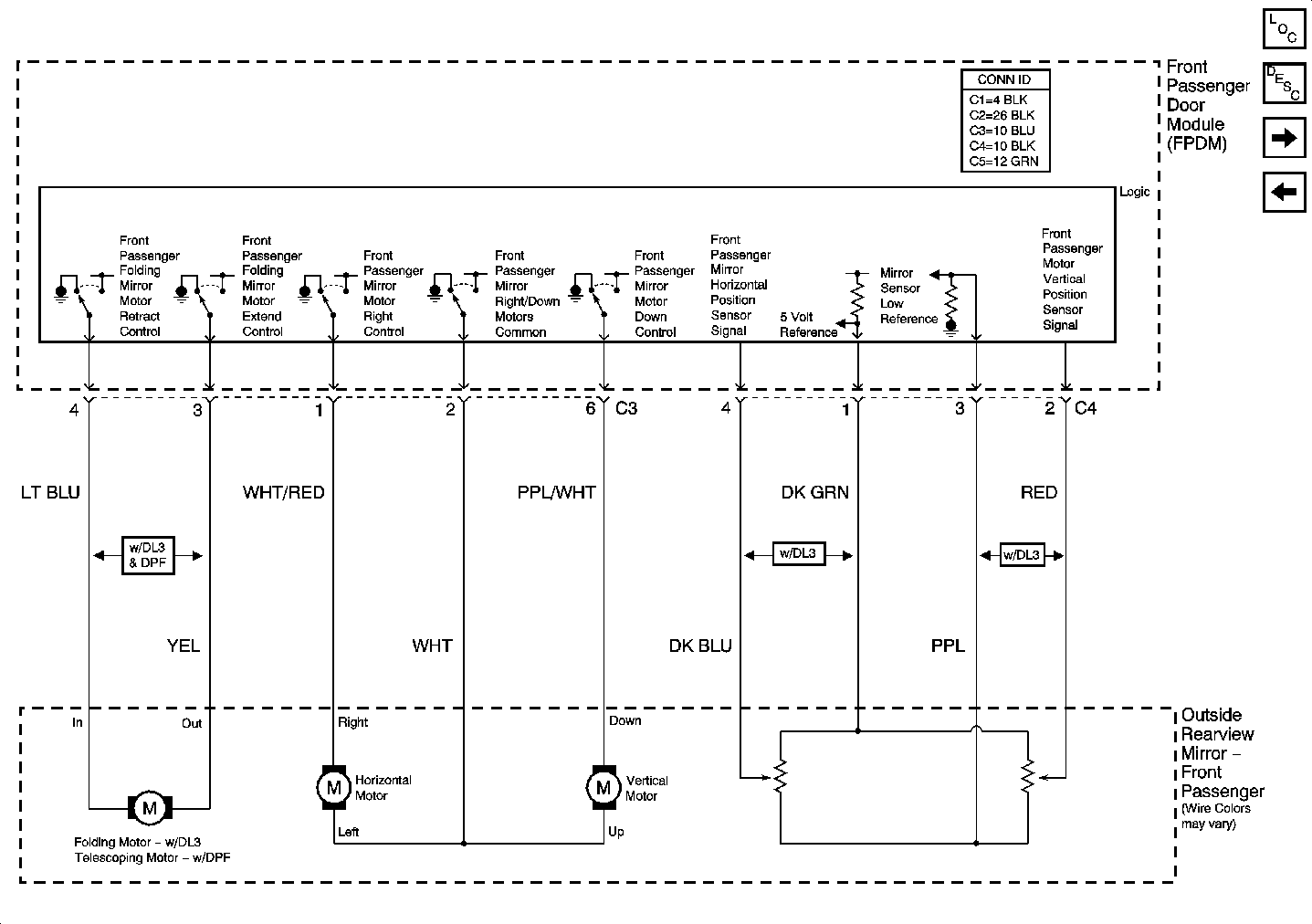
Front Passenger Door Module (FPDM) - C3 - (Except Base)
Connector Part Information
6383393-7
10-Way F 0.64mm Unsealed AMP (BLU)
Pin
Wire Color
Circuit No.
Function
1
RED / WHT
--
Front Passenger Mirror Motor Right Control
2
WHT
--
Front Passenger Mirror Right/Down Motors Common
3
YEL
--
Front Passenger Folding Mirror Motor Extend Control
4
LT BLU
--
Front Passenger Folding Mirror Motor Retract Control
5
ORN/BLK
--
Right Door Exterior Courtesy Lamp Supply Voltage
6
PPL/WHT
--
Front Passenger Mirror Motor Down Control
7
ORN
--
Mirror Heating Element Supply Voltage
8
BLK
--
Front Passenger Heating Element Low Reference
9
BLK
--
Right Door Exterior Courtesy Lamp Ground
10
GRY/BLK
--
Right Turn Signal Control
Front Passenger Door Module (FPDM) - C4 - (Except Base)
Connector Part Information
6383393-5
10-Way F 0.64mm Unsealed AMP (BLK)
Pin
Wire Color
Circuit No.
Function
1
DK GRN
--
5 Volt Reference
2
RED
--
Front Passenger Mirror Vertical Position Sensor Signal
3
PPL
--
Mirror Sensor Low Reference
4
DK BLU
--
Front Passenger Mirror Horizontal Position Sensor Signal
5
BRN/WHT
--
Right Turn Signal Low Reference
6-10
--
--
Not Used
Driver Door Module (DDM) - C3 - (Except Base)
Connector Part Information
6383393-7
10-Way F 0.64mm Unsealed AMP (BLU)
Pin
Wire Color
Circuit No.
Function
1
BRN/WHT
--
Left Turn Signal Low Reference
2
GRY/BLK
--
Left Turn Signal Control
3
BLK
--
Driver Mirror Heating Element Low Reference
4
PPL
--
Mirror Sensor Low Reference
5
--
--
Not Used
6
ORN/BLK
--
Left Door Exterior Courtesy Lamp Supply Voltage
7
GRY
--
Automatic Day/Night Mirror Signal
8
PNK
--
Automatic Day/Night Mirror Low Reference
9
BLK
--
Left Door Exterior Courtesy Lamp Ground
10
--
--
Not Used
Driver Door Module (DDM) - C4 - (Except Base)
Connector Part Information
6383393-5
10-Way F 0.64mm Unsealed AMP (BLK)
Pin
Wire Color
Circuit No.
Function
1
YEL
--
Driver Folding Mirror Motor Extend Control
2
ORN
--
Mirror Heating Element Supply Voltage
3
RED
--
Driver Mirror Horizontal Position Sensor Signal
4
DK GRN
--
5 Volt Reference
5
DK BLU
--
Driver Mirror Vertical Position Sensor Signal
6
LT BLU
--
Driver Folding Mirror Motor Retract Control
7
YEL
--
Driver Mirror Right/Down Motors Common
8
LT BLU
--
Driver Mirror Motor Right Control
9
GRN
--
Driver Mirror Motor Down Control
10
--
--
Not Used
------------------------------------------------------------------------
Front Passenger Door Module (FPDM) - C3 - (Except Base)
Connector Part Information
6383393-7
10-Way F 0.64mm Unsealed AMP (BLU)
Pin
Wire Color
Circuit No.
Function
1
RED / WHT
--
Front Passenger Mirror Motor Right Control
2
WHT
--
Front Passenger Mirror Right/Down Motors Common
3
YEL
--
Front Passenger Folding Mirror Motor Extend Control
4
LT BLU
--
Front Passenger Folding Mirror Motor Retract Control
5
ORN/BLK
--
Right Door Exterior Courtesy Lamp Supply Voltage
6
PPL/WHT
--
Front Passenger Mirror Motor Down Control
7
ORN
--
Mirror Heating Element Supply Voltage
8
BLK
--
Front Passenger Heating Element Low Reference
9
BLK
--
Right Door Exterior Courtesy Lamp Ground
10
GRY/BLK
--
Right Turn Signal Control
Front Passenger Door Module (FPDM) - C4 - (Except Base)
Connector Part Information
6383393-5
10-Way F 0.64mm Unsealed AMP (BLK)
Pin
Wire Color
Circuit No.
Function
1
DK GRN
--
5 Volt Reference
2
RED
--
Front Passenger Mirror Vertical Position Sensor Signal
3
PPL
--
Mirror Sensor Low Reference
4
DK BLU
--
Front Passenger Mirror Horizontal Position Sensor Signal
5
BRN/WHT
--
Right Turn Signal Low Reference
6-10
--
--
Not Used
Posted: February 14, 2005 at 4:52 AM / IP Logged
Posted: February 14, 2005 at 4:55 AM / IP Logged
Sorry, you can NOT post a reply.
This topic is closed.
 Printable version
| You cannot post new topics in this forum You cannot reply to topics in this forum You cannot delete your posts in this forum You cannot edit your posts in this forum You cannot create polls in this forum You cannot vote in polls in this forum |

| Search the12volt.com |
Follow the12volt.com 
Thursday, May 7, 2026 • Copyright © 1999-2026 the12volt.com, All Rights Reserved • Privacy Policy & Use of Cookies

Thursday, May 7, 2026 • Copyright © 1999-2026 the12volt.com, All Rights Reserved • Privacy Policy & Use of Cookies
Disclaimer:
*All information on this site ( the12volt.com ) is provided "as is" without any warranty of any kind, either expressed or implied, including but not limited to fitness for a particular use. Any user assumes the entire risk as to the accuracy and use of this information. Please
verify all wire colors and diagrams before applying any information.
