the12volt.com spacer
icon

relay auto start


Post ReplyPost New Topic
< Prev Topic Next Topic >
dxplicitone 
Member - Posts: 10
Member spacespace
Joined: November 08, 2002
Location: United States
Posted: November 08, 2002 at 12:52 AM / IP Logged  

hello to all... ive been installing quite some time on the side as a hobby and would like to take a shot at wiring an auto start from a relay combonation... ive installed numerous modules and love the units but this install is more for my piece of mind knowing i can do this rather than ease for myself or the user. ive done alot but never have done everything... im trying to get there eventually...

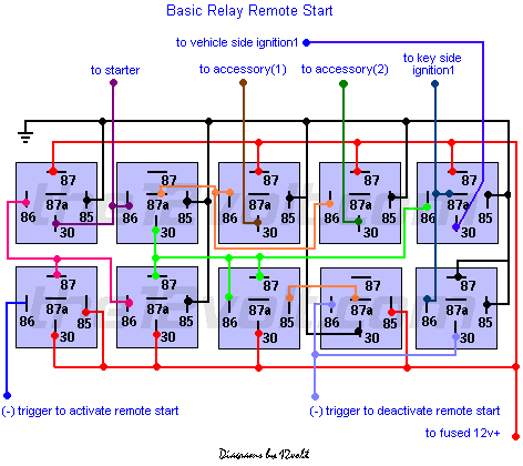
relay auto start -- posted image.

this is the piece of work as i see it here on the12volt... my questions.. are.. the ignition imputs... one is a key side and the other is a vehicle side... for what reason would i have both of these connections when using a module i never ran by anything of this nature... im taking this is the true igniton wire and i would be cutting it as if a were doing a starter kill and i have my key side / starter side... am i correct in thinking this?

and also.. i swore that ive seen this pulled off with fewer relays... or am i wrong? because god knows i do not want to try to stuff that in my dash! after i learn this i will be following up with that... 1 output to 4 output diagram next.. i hope i can find the answers im looking for. thank you in advance for your efforts and advice...

whats this wire do ??? poof.. ohhhhh!
dxplicitone 
Member - Posts: 10
Member spacespace
Joined: November 08, 2002
Location: United States
Posted: November 08, 2002 at 12:53 AM / IP Logged  
now why didnt my picture pop up?
whats this wire do ??? poof.. ohhhhh!
cpgoose 
Gold - Posts: 1,098
Gold spacespace
Joined: July 08, 2002
Location: United States
Posted: November 13, 2002 at 7:39 AM / IP Logged  

i guess you meant this picture?

relay auto start -- posted image.

I wouldn't really use that.  I would buy a remote starter module instead...that way you  know it will work, and you'll have more features (like tach monitoring, shut down after so many minutes, stuff like that).

Player69 
Silver - Posts: 504
Silver spacespace
Joined: October 27, 2002
Posted: November 13, 2002 at 7:27 PM / IP Logged  
I agree with cpgoose.   I don't see why you would use this.
Chris Luongo 
Platinum - Posts: 3,746
Platinum spaceThis member consistently provides reliable informationspace
Joined: May 21, 2002
Location: Massachusetts, United States
Posted: November 13, 2002 at 9:15 PM / IP Logged  

He already said why he wants to do this.

dxp, I've studied this diagram a little bit; it sure is complex and fascinating at the same time.  Anyway, look at the bottom right relay.  Turning the car's key to Run activates this relay, which in turn places a ground on the light blue wire, which deactivates the remote start, so the car can then be driven under its own power.

Player69 
Silver - Posts: 504
Silver spacespace
Joined: October 27, 2002
Posted: November 13, 2002 at 9:22 PM / IP Logged  
One problem with this is that your starter will only crank for the exact length of the - out pulse of the alarm.  THis would work good if you had an output that would go to ground for the exact amount of time you hold the button but then you would have to hear the vehicle to know when to let go of the button.
91blaze 
Member - Posts: 27
Member spacespace
Joined: May 02, 2002
Location: United States
Posted: December 02, 2002 at 2:00 PM / IP Logged  
wouldnt there be some sort of way to wire in a tach sensor? like maybe have a log or constant signal from the alarm then when started something to break that connection? sorry if thats confusing.
the12volt 
Administrator - Posts: 3,955
Administrator spaceThis member has made a donation to the12volt.com. Click here for more info.spaceThis member has been recognized as an authority in Electrical Theory. Click here for more info.spaceThis member has been recognized as an authority in Mobile Audio and Video. Click here for more info.spaceThis member has been recognized as an authority in Mobile Security and Convenience. Click here for more info.spacespace
Joined: March 07, 2002
Location: Louisiana, United States
Posted: December 02, 2002 at 2:33 PM / IP Logged  

I created this long before remote starts where readily available as they are today. There are other shut down and safety features I purposely did not include in this diagram and I only show it as a reference to show what can be done with relays and a little imagination. It is not intended nor recommended to be used in place of the units available today, but only as a challenge and learning experience for installers and enthusiasts.

With all of the aftermarket units that are available today and for as little as they cost I strongly recommend using them instead of making your own. However, if you're up to the challenge, keep in mind the diagram only shows the basics of my design to get you started. It does not show diodes across the coils of the relays nor any of the other safety features that you should incorporate such as monitoring tach signal, safety/neutral wire, brake & parking brake inhibits, a timer, a single output to start and stop the unit, etc.

BTW, the time it takes to wire all of these relays with the additional features before you even install it will be about the same amount of time or more that it takes to install an aftermarket unit with all the goodies included. 

the12volt

SnomanF150 
Silver - Posts: 269
Silver spacespace
Joined: September 19, 2002
Location: United States
Posted: December 02, 2002 at 7:41 PM / IP Logged  
I remember doing a remote starter like that with all the brake shut downs and stuff.. also wiring it for one button start and stop.. that was a pain to figure out...... still have the diagram somewhere.... man that brings back memories from 13 or 14 years ago.... running my standard mazda truck into a bench... Jerry wasn't happy about that and Gator thought it was funny.. bastard..
George
David's Car Stereo
Baton Rouge, LA

Sorry, you can NOT post a reply.
This topic is closed.

  Printable version Printable version Post ReplyPost New Topic
You cannot post new topics in this forum
You cannot reply to topics in this forum
You cannot delete your posts in this forum
You cannot edit your posts in this forum
You cannot create polls in this forum
You cannot vote in polls in this forum

  •  
Search the12volt.com
Follow the12volt.com Follow the12volt.com on Facebook
Sunday, May 5, 2024 • Copyright © 1999-2024 the12volt.com, All Rights Reserved Privacy Policy & Use of Cookies
Disclaimer: *All information on this site ( the12volt.com ) is provided "as is" without any warranty of any kind, either expressed or implied, including but not limited to fitness for a particular use. Any user assumes the entire risk as to the accuracy and use of this information. Please verify all wire colors and diagrams before applying any information.

Secured by Sectigo
the12volt.com spacer
Support the12volt.com
Top
the12volt.com spacer