the12volt.com spacer
icon

Relay for 2nd A/C condenser fan problem


Post ReplyPost New Topic
< Prev Topic Next Topic >
agentjam 
Member - Posts: 6
Member spacespace
Joined: January 28, 2004
Location: United States
Posted: June 30, 2005 at 11:04 PM / IP Logged  

Currently I have a radiator fan that comes on both when the temp gets above a certian point AND when the a/c compresser kicks on.  The condenser fan for A/C is now hooked up to nothing.  I want both to operate in the same manner, when either the A/C kicks on or the temps get above normal.

Here's where i got to...I have the POS/NEG wires going to the working radiator fan sitting in front of me.

So...i cut the POS radiator fan wire and hooked the POS feed to pin 86 wire the fan side connected to 85 (so the current flows through relay).

Next i hooked the A/C condenser fan POS to pin 30, with the remaining pin 87 hooked to a constant 12V.

Is this correct?  The second fan will not kick on and when the first (radiator) fan turns on the relay isn't popping the bridge across pins 30 and 87. 

I also thought that maybe the POS of the radiator fan shouldn't be cut and ran through the ralay but just simply have a branch of the 12V from the radiator fan at pin 86, in that case i hooked pin 85 to ground but everytime the first fan went on I blew a fuse.

I'm lost, i've used relay's before in similar applications but for some reason i can't get the 12V to bridge to my second fan.

PS - I've tested the 2nd fan with 12V and it runs, used my voltmeter to narrow it down to the pins 30/87 not getting continuity.

Thanks,

Vince

87 (Yellow) Power Positive (+)

86 (Black) Ignition Switch (+)
30 (Blue Wire) Out put to Fan (+)
85 (White) Ground from Temperature Sensor (-)

agentjam 
Member - Posts: 6
Member spacespace
Joined: January 28, 2004
Location: United States
Posted: June 30, 2005 at 11:06 PM / IP Logged  

Ignore the bottom lines about the temp sensor, i was just using that as a guide when writing the post.

Thanks,

Vince

agentjam 
Member - Posts: 6
Member spacespace
Joined: January 28, 2004
Location: United States
Posted: July 01, 2005 at 6:03 AM / IP Logged  
hmm noone?
Mad Scientists 
Silver - Posts: 380
Silver spacespace
Joined: February 07, 2004
Location: United States
Posted: July 01, 2005 at 7:43 PM / IP Logged  

agentjam wrote:

I also thought that maybe the POS of the radiator fan shouldn't be cut and ran through the ralay but just simply have a branch of the 12V from the radiator fan at pin 86, in that case i hooked pin 85 to ground but everytime the first fan went on I blew a fuse.

87 (Yellow) Power Positive (+)

86 (Black) Ignition Switch (+)
30 (Blue Wire) Out put to Fan (+)
85 (White) Ground from Temperature Sensor (-)

This part about wiring the fan to the relay is correct.. pin 86 to Fan #1 positive (this assumes that the positive wire on Fan #1 is switched and that it's not the ground that's being switched) and Pin 85 to ground.. This should energize the relay.  What fuse are you blowing?.. check to make sure that pin 87 isn't grounded and the circuit powering pin 30 is the one popping the fuse..

Questions?..

(Sorry I didn't get back to your posting earlier.. between midnight and 7 am I was sleeping and went straight to work.. )

Jim

Hoptup32 
Copper - Posts: 87
Copper spacespace
Joined: December 25, 2004
Location: United States
Posted: July 02, 2005 at 8:47 AM / IP Logged  

Your second idea was following the correct logic to activate the AC fan relay, you must have something wired up incorrectly to be blowing a fuse.

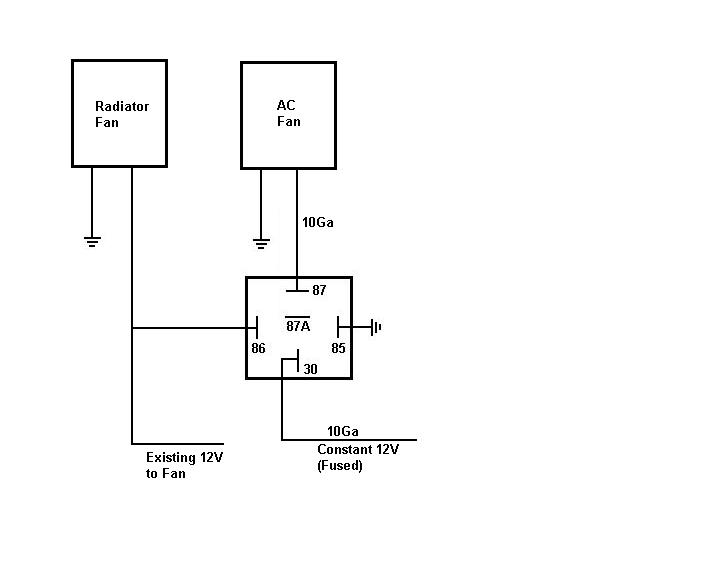
I have attached a diagram as a guide for the AC fan relay wiring.  Reconnect the positive feed back up to the radiator fan and just connect a feed from the positive fan wire to relay terminal 86 to activate the AC fan relay when the radiator fan comes on. The feed wire to terminal 86 can be a small gauge wire, like 16-18ga as the relay will only need a few hundred milliamps to activate, so I can't understand why you are blowing a fuse.  Then following the diagram, wire the AC fan positive to terminal 87 and the constant 12v feed to terminal 30, with 85 being a simple ground.

The important thing to pay attention to is the connection to the radiator fan positive wire to the relay terminal 86 has to be made somewhere along the the wire going directly to the radiator fan, after whatever wiring is controlling this fan.  Since the radiator fan was working correctly, in regards to coming on with the temp sensor and the AC compressor, you want to make sure you connect the wire to relay terminal 86 from the power feed to the radiator fan after the relay(s) that are currently controlling the radiator fan. Then the AC fan should kick in when the radiator fan comes on.

Relay for 2nd A/C condenser fan problem - Last Post -- posted image.

agentjam 
Member - Posts: 6
Member spacespace
Joined: January 28, 2004
Location: United States
Posted: July 02, 2005 at 4:58 PM / IP Logged  

Thank you both,  I'm pretty sure i hooked it up wrong the first time and possibly blown the relay...I think the first time i ran the power wire for the rad fan through the 85-86 pins and ruined it.  Then when i corrected it the relay would totally ground out the 12v switched blowing my rad fan fuse.

Thanks again guys, i grabbed another relay hopefully it'll be smooth sailing!

Vince

ken1959 
Member - Posts: 3
Member spacespace
Joined: June 20, 2004
Location: Canada
Posted: July 16, 2005 at 8:36 AM / IP Logged  
I don't know why you are doing this but I assume your ac system is still working. I hope you realize that when your ac system turns on and requests the condenser fan. It will not come on. It will only come on when engine coolant temperature requests the rad fan. This will cause the high side pressure of the ac system too go very high, 400psi or more.
continued operation will result in either the safety valve on the compressor to release freon to the atmosphere, damaged compressor or pressure failure to any of the ac system components. Working on the car and having your face near these components when they burst is not something I recomend. I have been making my living as an automotive tech for 25 years, and my suggestion is not to do this unless your understand how the ac system works
Hoptup32 
Copper - Posts: 87
Copper spacespace
Joined: December 25, 2004
Location: United States
Posted: July 16, 2005 at 10:38 AM / IP Logged  

ken1959, I agree with your post 100%. The when the ac compressor turns on, whatever fan is to cool the condenser should come at the same time, for the reasons you mentioned.

Agentjam's post says that the radiator fan currently does comes on when the when the ac compressor is turned on AND when th temp sensor activates  .  So his radiator fan activation seems to be working correctly, as per your suggestion. 

The impression I got from his post is that his additional ac condensor fan was not currently hooked up to anything.  The diagram I posted was a very simple hookup to turn on the extra ac condensor fan when the radiator fan comes on, either with the temp sensor or when the ac compressor turns the radiator fan on.  The 12v to the relay must be tapped to the radiator fan output source after whatever temp sensor or ac compressor activation is currently controlling the radiator fan.

It wasn't my intent for him to rewire the fans completely with the diagram I posted,  but rather to use it to simplfy the activation of the supplemental ac condensor fan.


Sorry, you can NOT post a reply.
This topic is closed.

  Printable version Printable version Post ReplyPost New Topic
You cannot post new topics in this forum
You cannot reply to topics in this forum
You cannot delete your posts in this forum
You cannot edit your posts in this forum
You cannot create polls in this forum
You cannot vote in polls in this forum

  •  
Search the12volt.com
Follow the12volt.com Follow the12volt.com on Facebook
Sunday, April 28, 2024 • Copyright © 1999-2024 the12volt.com, All Rights Reserved Privacy Policy & Use of Cookies
Disclaimer: *All information on this site ( the12volt.com ) is provided "as is" without any warranty of any kind, either expressed or implied, including but not limited to fitness for a particular use. Any user assumes the entire risk as to the accuracy and use of this information. Please verify all wire colors and diagrams before applying any information.

Secured by Sectigo
the12volt.com spacer
Support the12volt.com
Top
the12volt.com spacer