the12volt.com spacer
icon

Gentex 261 Hook Up


Post ReplyPost New Topic
< Prev Topic Next Topic >
hat_15 
Member - Posts: 5
Member spacespace
Joined: November 08, 2005
Posted: November 08, 2005 at 7:01 PM / IP Logged  

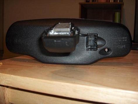
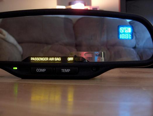
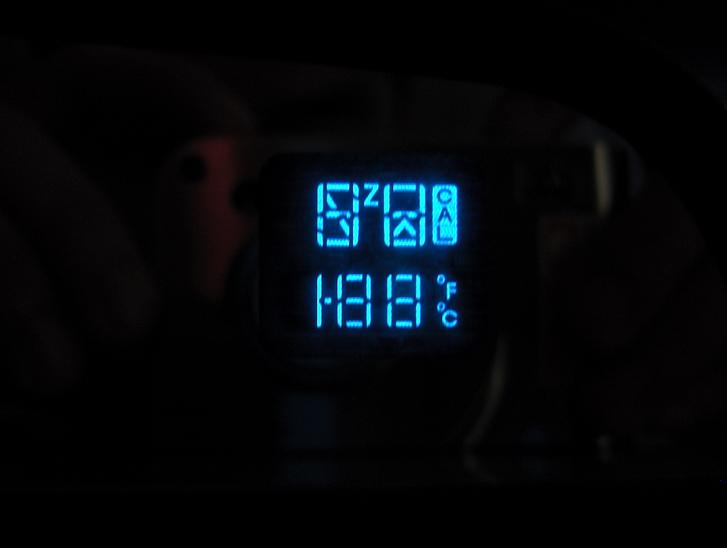
I've searched and read the long thread about this. I have a 16 pin connector on my mirror. What is the bare minimum to get this mirror to work properly? I had the power wire to pin 13 and ground to pin 8. It lit up the display but stayed lit up, like everything in the display stayed lit. Didn't have temp sensor hooked up at the time. Will that stop my mirror from not functioning or is the mirror I have messed up? It's a auto-dim with compass and temp readout. It's a Gentex 261. Here are some pics as to what I'm talking about. Last two pics is what is displayed the whole time it is on when just having a power and ground to it.

Gentex 261 Hook Up -- posted image.

Gentex 261 Hook Up -- posted image.

Gentex 261 Hook Up -- posted image.

Gentex 261 Hook Up -- posted image.

apex_189 
Member - Posts: 2
Member spacespace
Joined: November 08, 2005
Location: United States
Posted: November 09, 2005 at 7:08 AM / IP Logged  
i have the same mirror in my.looks like whats in most gms.let me know what its out of and i can send u the wiring diagram and a chart showing what each pin is used for.oh yeah i work at a gm dealer.
hat_15 
Member - Posts: 5
Member spacespace
Joined: November 08, 2005
Posted: November 09, 2005 at 7:41 AM / IP Logged  

Well the thing was, I bought it on eBay and they were kinda generic about what vehicle it came out of. It listed CHEVY,GMC,TRUCK,YUKON. But it's just autodim, compass, temp, and nothing else. I searched before and found this for a wire diagriam:

Pin 1-not used

2 - Microphone (if the mirror is equipped with it)

3 - "Passenger Air Bag on" notification (if mirror is equipped with that display)

4. - "Passenger Air Bag off" notification (if mirror is equipped with that display)

5 - auto day/night signal, which comes from the LH outside rearview mirror

6 - Temp probe connection ( if mirror is equipped with display)

7 - Temp probe connection (if mirror is equipped with display)

8 -  Ground

9 -  one source says it's a Reverse Dim Inhibit signal so the mirror will not dim when the vehicle is in reverse, another says it's a supply voltage from a back-up supply (I guess so Onstar will still work in the event that the main evehicle battery is disabled in an accident). I'm pretty sure if 12v is applied to this pin, the mirror will not dim no matter what.

10 - Microphone (if mirror is equipped) 

11- keypad signal (out) for On-star (pressing any button puts out a 5v multiplexed signal on this pin, - so you can't just use the buttons to control whatever you want to. Sorry.)

12 - keypad supply (5v) voltage (in) for the buttons

13 - ignition voltage (12v -main power IN to the mirror)

14 - keypad green LED signal

15  - keypad red LED signal

16 - return line to the LH outside mirror for day/night signal

I hooked up pin 8 for ground and 13 for power and I get power to it but just everything stays lit like the above pic. Let me know what else I need to hook up. Thanks.

hat_15 
Member - Posts: 5
Member spacespace
Joined: November 08, 2005
Posted: November 09, 2005 at 8:19 PM / IP Logged  
Just got an email from seller saying the mirror is out of a 2002 Chevy truck. No specific model. Hope that helps so I can get this mirror up and running right.
hat_15 
Member - Posts: 5
Member spacespace
Joined: November 08, 2005
Posted: November 11, 2005 at 4:56 PM / IP Logged  
Anyone??? I'm about to just get rid of it since I can't do anything with it. apex_189...what did you hook up on yours to make it work? Can I just get by with a temp sensor  and nothing else?
hat_15 
Member - Posts: 5
Member spacespace
Joined: November 08, 2005
Posted: November 29, 2005 at 6:48 PM / IP Logged  
I've seen exact mirror that I have out of 2006 Chevy Silverado 2500 4Dr. So if anyone has wiring diagram specific for that truck and mirror, let me know. I know someone has to have info about this being that this thread was looked at over 100 times.
earlybroncoguy 
Member - Posts: 4
Member spacespace
Joined: January 21, 2004
Location: United States
Posted: December 17, 2005 at 9:37 PM / IP Logged  

I posted that wiring pinout description about a year ago, after buying several used Onstar mirrors on eBay and spending a few hours figuring everything out.

In order for the temp/compass display to work properly, you'll have to hook up the factory temp probe to the mirror at pins 6 & 7. The compass is built into the mirror, and should work properly once power is applied and the compass is calibrated. I'm pretty sure you hold down the "comp" button for a few seconds until it enters the calibration mode, then slowly turn the entire mirror in several 360 circles until the display starts to show the correct direction.

If you can't get the temp/compass display to show anything other than having every segment lit up, the circuit board is most likely bad.

You can check the auto-dimming feature by putting the mirror into a dark room, hooking up power to it, then shining a bright light at the mirror glass and checking your reflection. You should see the mirror glass start to dim slowly. The reason you have to be in a dark room is that the mirror won't dim if it senses it's daylight outside - that's what the sensor on the FRONT of the mirror is for.

You can change the "airbag on" or "off" display by applying a ground to either pin 3 or 4, depending on which you want.  

fgy33 
Member - Posts: 1
Member spacespace
Joined: August 17, 2005
Location: United States
Posted: January 20, 2006 at 3:04 AM / IP Logged  

earlybroncoguy wrote:
In order for the temp/compass display to work properly, you'll have to hook up the factory temp probe to the mirror at pins 6 & 7. The compass is built into the mirror, and should work properly once power is applied and the compass is calibrated.

If I don't hook up the temp sensor, will the compass work?


Sorry, you can NOT post a reply.
This topic is closed.

  Printable version Printable version Post ReplyPost New Topic
You cannot post new topics in this forum
You cannot reply to topics in this forum
You cannot delete your posts in this forum
You cannot edit your posts in this forum
You cannot create polls in this forum
You cannot vote in polls in this forum

  •  
Search the12volt.com
Follow the12volt.com Follow the12volt.com on Facebook
Friday, May 3, 2024 • Copyright © 1999-2024 the12volt.com, All Rights Reserved Privacy Policy & Use of Cookies
Disclaimer: *All information on this site ( the12volt.com ) is provided "as is" without any warranty of any kind, either expressed or implied, including but not limited to fitness for a particular use. Any user assumes the entire risk as to the accuracy and use of this information. Please verify all wire colors and diagrams before applying any information.

Secured by Sectigo
the12volt.com spacer
Support the12volt.com
Top
the12volt.com spacer