the12volt.com spacer
icon

Wiring Door lock relays


Post ReplyPost New Topic
< Prev Topic Next Topic >
don4501 
Member - Posts: 5
Member spacespace
Joined: May 08, 2002
Location: Canada
Posted: December 18, 2002 at 1:47 PM / IP Logged  

I am trying to wire up my compustar lcd type alarm to lock/unlock the doors of my 00 Jimmy.

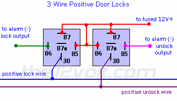
The alarm output is (-). So i have used a relay for each lock/unlock to convert to a (+).

http://members.shaw.ca/donaldewasko/convert.jpg   (From Jeff @ Velocity)

I tried the neg input-->pos output diagram. The problem i get is 12v feeding back to the outs on the alarm. Now I'm thinking that it should be neg output-->pos out   not  neg input-->pos out?

How should i wire the relay to change the neg of the alarm leads to pos for the door lock/unlock wires. Would i need a diode to prevent the current going to the alarm or what did i wire wrong.

Thanks Donald

jrilla 
Gold - Posts: 1,498
Gold spaceThis member has made a donation to the12volt.com. Click here for more info.spacespace
Joined: November 19, 2002
Location: North Dakota, United States
Posted: December 18, 2002 at 2:16 PM / IP Logged  

Wiring Door lock relays - Last Post -- posted image.

Negative input means input for the relay, but you use your negative output from the alarm. This diagram works.

J Rilla
Owner/Installer
don4501 
Member - Posts: 5
Member spacespace
Joined: May 08, 2002
Location: Canada
Posted: December 18, 2002 at 3:51 PM / IP Logged  

I have tried this but get 12V on the wires that connect to the alarm and this will cause damage to the alarm. What can i do to stop this/is this normal. Is it possible that i have a wrong type of relay. They are the same shape with the same config of terminals as the diagram you provided but I don't know what to do to stop the current from travelling back to my alarm and ruining it.

Thanks for the post

Donald

demeanor 
Copper - Posts: 81
Copper spacespace
Joined: December 10, 2002
Location: United States
Posted: December 18, 2002 at 4:14 PM / IP Logged  
try blocking the feedback to the alarm brain with a diode.
It's better to ask a "STUPID" question...than to know a "STUPID" answer. :-)
don4501 
Member - Posts: 5
Member spacespace
Joined: May 08, 2002
Location: Canada
Posted: December 18, 2002 at 4:20 PM / IP Logged  

How should the diode be installed. I don't really understand the instructional link on Diodes.

The side with the stripe should be where?

Thanks again

Don

don4501 
Member - Posts: 5
Member spacespace
Joined: May 08, 2002
Location: Canada
Posted: December 18, 2002 at 11:26 PM / IP Logged  
i have installed the diode now and it will block the flow of current towards the alarm but it will not allow the ground signal to reach the relay. what am i doing wrong.
jrilla 
Gold - Posts: 1,498
Gold spaceThis member has made a donation to the12volt.com. Click here for more info.spacespace
Joined: November 19, 2002
Location: North Dakota, United States
Posted: December 19, 2002 at 8:09 AM / IP Logged  

That is because you do not need a diode.  Your diode is preventing positve flow toward the alarm right? This means that it allows negative flow toward the alarm though right? Which also means that it prevents negative flow from the alarm to the relay.  Which brings up the question I had earlier but never posted, why do you think your alarm will be ruined? They are outputs, and all you are doing is energizing a coil in the relay.  just hook it up and you will be fine.  Imagine if your car had negative door locks, you would just tap into those wires and those wires have 12v+ on them until you hit the switch and ground it.  Have you actually tried hooking up the relay diagram above or did you just think about it before you tried it and stopped?

J Rilla
Owner/Installer
don4501 
Member - Posts: 5
Member spacespace
Joined: May 08, 2002
Location: Canada
Posted: December 19, 2002 at 8:35 AM / IP Logged  

J,

I did hook it up for approx 10 sec. there was some smoke and an awful burning smell. I opened up the CPU and on the board about where the lock/unlock leads enter in this order plug--small capacitor(?)--then a small rectangle shapped block about 2-3mm in size. It was this block that sort of melted. So I am assuming it was the 12v feeding back through the locks that did it :(

As an installer you come up to wiring keyless entry what needing (-) to (+) do you use two relays? No diodes? Cause i don't believe this should be so difficult. As I'm allmost in tears cause I cant figure this damn thing out.

In retrospect, I am ASSUMING it was the locks that caused the burning problem, because I have been over the wiring and all the other wires seem to be wired correctly and the main power leads are all fused so ?

-Don

jrilla 
Gold - Posts: 1,498
Gold spaceThis member has made a donation to the12volt.com. Click here for more info.spacespace
Joined: November 19, 2002
Location: North Dakota, United States
Posted: December 19, 2002 at 8:45 AM / IP Logged  

Did it smoke just by hooking it up, or after you push the lock button did it start to smoke? In other words can you hook it up according to the relay diagram and just let it sit there and be fine? or does it smoke just by hooking it up?.  if you hooked it up according to the relay diagram, then your lock and unlock output is not doing anything until you push a button on your transmitter. 

J Rilla
Owner/Installer

Sorry, you can NOT post a reply.
This topic is closed.

  Printable version Printable version Post ReplyPost New Topic
You cannot post new topics in this forum
You cannot reply to topics in this forum
You cannot delete your posts in this forum
You cannot edit your posts in this forum
You cannot create polls in this forum
You cannot vote in polls in this forum

  •  
Search the12volt.com
Follow the12volt.com Follow the12volt.com on Facebook
Tuesday, May 21, 2024 • Copyright © 1999-2024 the12volt.com, All Rights Reserved Privacy Policy & Use of Cookies
Disclaimer: *All information on this site ( the12volt.com ) is provided "as is" without any warranty of any kind, either expressed or implied, including but not limited to fitness for a particular use. Any user assumes the entire risk as to the accuracy and use of this information. Please verify all wire colors and diagrams before applying any information.

Secured by Sectigo
the12volt.com spacer
Support the12volt.com
Top
the12volt.com spacer