the12volt.com spacer
icon

Is my relay setup configured correctly?


Post ReplyPost New Topic
< Prev Topic Next Topic >
maxima lover 
Member - Posts: 8
Member spacespace
Joined: October 07, 2005
Location: United States
Posted: February 01, 2006 at 3:25 PM / IP Logged  
I'm helping a couple of friends with a mini formula car they are building for their school. They want to be able to switch gears using the push buttons on the steering wheel. They already have the motor setup to change the gears correctly on their Kawasaki engine, but needed some help with the wiring. I am not to familiar with capacitors, but I think my setup is right.
I made it so it will release the entire capacitor load and then switch back to the battery to recharge. If the 2nd button is pressed, the power is reversed on the motor. I would appreciate if you could make sure my setup will work and if not, what I need to change. Also, is there an easier way?
Is my relay setup configured correctly? - Last Post -- posted image.
hotwaterwizard 
Silver - Posts: 1,350
Silver spacespace
Joined: December 11, 2003
Location: California, United States
Posted: February 02, 2006 at 1:45 AM / IP Logged  

Explain better.

I understand it as follows.

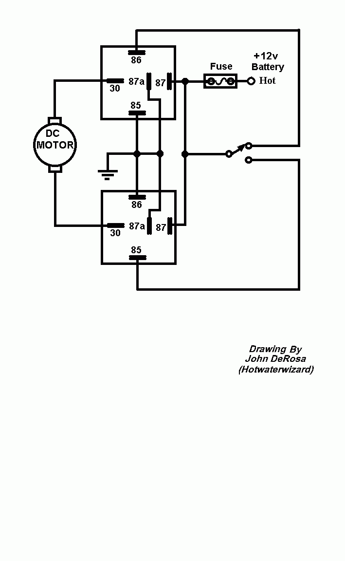
You have one motor that you want to control the forward and reverse with relays and push buttons. Right?

You can do it with 2 relays.

Is my relay setup configured correctly? - Last Post -- posted image.

John DeRosa (Hotwaterwizard)
Stockton California
When in doubt, try it out !
maxima lover 
Member - Posts: 8
Member spacespace
Joined: October 07, 2005
Location: United States
Posted: February 02, 2006 at 2:07 AM / IP Logged  
hotwaterwizard wrote:

Explain better.

I understand it as follows.

You have one motor that you want to control the forward and reverse with relays and push buttons. Right?

You can do it with 2 relays.

Thanks for the reply.
I do want to have two pushbuttons that control the motor two ways, but I want it to go a certain amount of time (about 1 second) no matter how short or long the button is pressed. That is why I used the capacitor. If I press the button 1/2 second or 5 seconds it will still only send power for 1 second. Then when the button is released, it would allow the capacitor to charge up again.
BTW I can't use a timer relay bceause it is going to have to be more exact then 1 second.
hotwaterwizard 
Silver - Posts: 1,350
Silver spacespace
Joined: December 11, 2003
Location: California, United States
Posted: February 02, 2006 at 2:13 AM / IP Logged  
Is my relay setup configured correctly? - Last Post -- posted image.
John DeRosa (Hotwaterwizard)
Stockton California
When in doubt, try it out !
maxima lover 
Member - Posts: 8
Member spacespace
Joined: October 07, 2005
Location: United States
Posted: February 02, 2006 at 2:43 AM / IP Logged  
hotwaterwizard wrote:
[URL=https://www.the12volt.com/installbay/uploads/55E_off_relay.gif] https://www.the12volt.com/installbay/uploads/55E_off_relay.gif
I'm sorry, but I really don't think I understand this diagram. Could you please explain it. Thanks.
hotwaterwizard 
Silver - Posts: 1,350
Silver spacespace
Joined: December 11, 2003
Location: California, United States
Posted: February 02, 2006 at 8:59 AM / IP Logged  

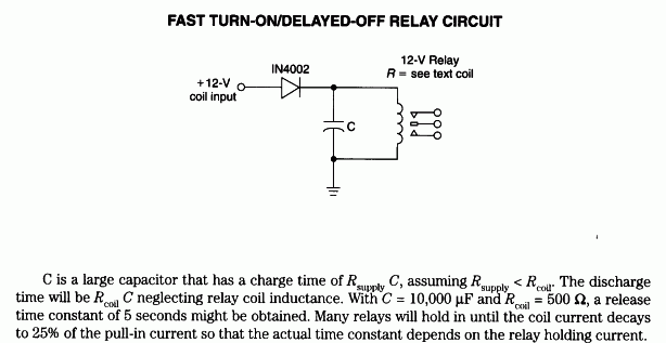
The Time it takes to discharge the capacitor is explained in detail in the picture.

It gives you the mathimatical formula to figure out how long it will take to release the relay coil. The picture is also the correct way of accomplishing the task.

In other words it explains how to change the time the relay is on before it goes off. And how to hook up the relay to do that.

John DeRosa (Hotwaterwizard)
Stockton California
When in doubt, try it out !
hotwaterwizard 
Silver - Posts: 1,350
Silver spacespace
Joined: December 11, 2003
Location: California, United States
Posted: February 02, 2006 at 8:50 PM / IP Logged  

Is this the pinout you used for your drawing?

85 = Coil

86 = Coil

87 = Normal OPEN

87a = Normal Closed

30 = Common

Is my relay setup configured correctly? - Last Post -- posted image.

John DeRosa (Hotwaterwizard)
Stockton California
When in doubt, try it out !
auex 
Platinum - Posts: 5,041
Platinum spaceThis member has made a donation to the12volt.com. Click here for more info.spacespace
Joined: December 23, 2002
Location: Arizona, United States
Posted: February 02, 2006 at 9:09 PM / IP Logged  
Is there still going to be a clutch?
Certified Security Specialist
Always check info with a digital multimeter.
I promise to be good.
Tell Darwin I sent you.
I've been sick lately, sorry I won't be on much.
maxima lover 
Member - Posts: 8
Member spacespace
Joined: October 07, 2005
Location: United States
Posted: February 02, 2006 at 10:33 PM / IP Logged  
hotwaterwizard wrote:

Is this the pinout you used for your drawing?

85 = Coil

86 = Coil

87 = Normal OPEN

87a = Normal Closed

30 = Common

Is my relay setup configured correctly? - Last Post -- posted image.

I made 87a always connected to 30. Only time 30 is connected to 87 is when there is a charge through 85 and 86. This is the way every SPDT relay I have ever used has been set up.
maxima lover 
Member - Posts: 8
Member spacespace
Joined: October 07, 2005
Location: United States
Posted: February 02, 2006 at 10:35 PM / IP Logged  
auex wrote:
Is there still going to be a clutch?
Yes there is still a clutch. I'm not sure if it's going to be on the wheel or mounted in the floor.

Sorry, you can NOT post a reply.
This topic is closed.

  Printable version Printable version Post ReplyPost New Topic
You cannot post new topics in this forum
You cannot reply to topics in this forum
You cannot delete your posts in this forum
You cannot edit your posts in this forum
You cannot create polls in this forum
You cannot vote in polls in this forum

  •  
Search the12volt.com
Follow the12volt.com Follow the12volt.com on Facebook
Saturday, April 27, 2024 • Copyright © 1999-2024 the12volt.com, All Rights Reserved Privacy Policy & Use of Cookies
Disclaimer: *All information on this site ( the12volt.com ) is provided "as is" without any warranty of any kind, either expressed or implied, including but not limited to fitness for a particular use. Any user assumes the entire risk as to the accuracy and use of this information. Please verify all wire colors and diagrams before applying any information.

Secured by Sectigo
the12volt.com spacer
Support the12volt.com
Top
the12volt.com spacer