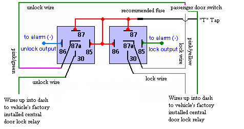
I searched and searched for info on installing a keyless entry system on my 2006 Ford Crown Victoria Police Interceptor and found no one had this info available. Well, I just went ahead and made an educated guess and got it right. So I will share it with those of you that are, or will be looking for this info since Ford in their infinite wisdom has decided that they will not offer keyless entry on their Police Interceptor model after 2002. Don't tell Ford Motor Company or your dealership your doing this because they don't like anyone but their people cutting into the vehicle wiring.
You will need to install the two relays as 5 wire alternating 12 volts positive locks with 2 single pole double throw relays (SPDT). 12volt has the diagram in which to wire the relays together at:
https://www.the12volt.com/doorlocks/page3.asp#5w
You will notice that the locks are pulsed by a relay that was factory installed from somewhere inside the car and that if you hold down the door lock switch that the relay releases the door lock actuator circuit even though you hold the button down to lock or unlock. This is not a problem as long as you are not installing a latching relay module (I don't know why you would). The best place I found to install the relays and control module is behind the glove box and behind the passenger side kick panel. There is plenty of work space there and very few moving parts to be concerned about. The wiring harness can be found behind the passenger side kick panel running up into the dash and over the glove box.
There are three wires you need to be concerned about. The first is the positive 12 volt wire feeding the door lock switch on the passenger door. This wire is a 16 gauge green wire with no trace. You need to use this to supply the power to the relays and power for door lock actuator. If you try to introduce power from another circuit into the door lock system it will cause blown fuses, fried relays and possibly a fried Lighting Control Module (LCM). The power from any other wire or source will cause a back feed into the LCM, overload the small 16 gauge wire and damage the vehicles wiring. You can “T” tap the green 16 gauge wire for the power to operate the keyless entry module as well as the keyless entry control module as long as the entire system does not exceed the allowable ampers of the vehicles circuit or the 16 gauge wire.
The next wire is the unlock wire. This wire is the 16 gauge pink with a green trace. You need to locate it and cut it and connect it as the illustration below shows. After the wire is cut the segment going up into the dash should receive positive 12 volts from the relays when the keyless entry module receives the signal to unlock (pin 30 or common). The relays should be wired so that when they are at rest the pink with a green trace wire passes through the relay to allow normal operation of the door locks. The end that goes to the door switch should connect to pin 87a or the nomally closed pin. There should be continuity between pin 87a and 30 when the coil in the relay is not energised or the relay is at rest. This is the unlock relay's configuration.
The next wire is the lock wire. This wire is the 16 gauge pink with a yellow trace. You need to locate it and cut it and connect it as the illustration shows. After the wire is cut the segment going up into the dash should receive positive 12 volts from the relays when the keyless entry module receives the signal to lock. The segement going up into the dash needs to be connected to pin 30 on the lock relay. The other segment going into the door and to the swich should be connected to pin 87a The relays should be wired so that when they are at rest the pink with a yellow trace wire passes through the relay to allow normal operation of the door locks.
One side of each coil, as shown in the diagram, and pin 87 should all be connected to the green 16 gauge wire. I recommed installing a fuse into the wiring for the vehices protection in case you get a junky alarm system, keyless entry module or have a relay coil go bad or somthing. This will keep the vehicle's wiring and electronic components protected. You can can and probably should put the keyless entry module on the added fuse as I did, though I did not put it in the drawing.

Good Luck / Work Safe!
 Printable version


