the12volt.com spacer
icon

led and diodes


Post ReplyPost New Topic
< Prev Topic Next Topic >
zee4speed 
Member - Posts: 5
Member spacespace
Joined: August 04, 2006
Location: United States
Posted: August 16, 2006 at 8:41 PM / IP Logged  
Depicted is a picture of a testlight I'ld like to create.
led and diodes - Last Post -- posted image.
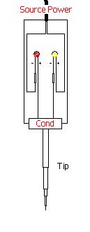
the "SourcePower" is connected to both positive and negative, and one can follow where they connect to the leds. The "Tip" of this testlight, can tap either positive or negative. The tapping of the powersource will determine which LED lights up. "Cond" Is basically a piece of metal conducting from the tip to both leds. However the problem Im having is that as soon as "SourcePower" is connected, both led's light up. I realized that because of "Cond", its allowing power to be passed between both LEDs. I believe that all I need is two DIODES. Connect one diode to each led between the "Cond" and LED.
So the question is, is this the correct approach? And also which way should I put the diodes in.
Please help.
KPierson 
Platinum - Posts: 3,527
Platinum spaceThis member consistently provides reliable informationspace
Joined: April 14, 2005
Location: Ohio, United States
Posted: August 16, 2006 at 10:27 PM / IP Logged  
LEDs are diodes, so you shouldn't need to add a diode as you already have the LEDs.  However, you will need to limit the current going to the LEDs for your specific voltage range.  Sizing this resistor may be difficult if trying to make the LEDs light up over a wide range of voltages.  If you are just interested in car voltages (5 and 12vdc) you shouldn't have much problems.  You will need the data sheet of the LED and the maximum working voltage to calculate the reesistance for each color of LED you use.
Kevin Pierson
Mad Scientists 
Silver - Posts: 380
Silver spacespace
Joined: February 07, 2004
Location: United States
Posted: August 18, 2006 at 1:08 PM / IP Logged  

LED polarity sensitive test lights are already on the market.. you could think of the LEDs on when you plug it in as a 'design feature' to verify you have voltage at the plug, or you could consider two current limiting resistors.. when the probe isn't touching anything the resistors are in series and drop enough current that the LEDs don't light, or come on dim.

Ask if you have any more questions..

Jim

Cameronjc 
Member - Posts: 29
Member spacespace
Joined: February 06, 2004
Posted: August 20, 2006 at 12:58 AM / IP Logged  

You are correct, using diodes will produce your desired effect.

I would use / recommend 1N4001. A bit much but they'll work just fine. In fact if you'd like a couple I'll mail them your way if you wanna cover the cost of the stamp.

Cameronjc 
Member - Posts: 29
Member spacespace
Joined: February 06, 2004
Posted: August 20, 2006 at 1:04 AM / IP Logged  
Oh and also, if you needed to know, the stripe stamped on one end of the diode indicates the polarity. (stripe indicates the cathode side).
Mad Scientists 
Silver - Posts: 380
Silver spacespace
Joined: February 07, 2004
Location: United States
Posted: August 20, 2006 at 5:37 PM / IP Logged  

How/where would you wire in the diodes?..

Cameronjc 
Member - Posts: 29
Member spacespace
Joined: February 06, 2004
Posted: August 20, 2006 at 11:34 PM / IP Logged  

You would put it inline from the conductor to the leds with the stripe facing the LEDs.

That way the diode resists the power coming from the LED's via the power source to the conductor, disrupting the circuit. That way the connductor is neither + or - until you touch it to whatever your probing.

zee4speed 
Member - Posts: 5
Member spacespace
Joined: August 04, 2006
Location: United States
Posted: August 23, 2006 at 11:32 AM / IP Logged  

Cameronjc

are you sure that would work?

Im not guru, and dont know too much, but a resistor allows positive to flow one way, and negative to flow the other way only.  So in my case look at the bulb on the right, the yellow one.  It currently gets negative from the red bulb, how could the diode keep it from completing the circuit from the red led's negative and not do the same from the conductors negative charge?

Cameronjc 
Member - Posts: 29
Member spacespace
Joined: February 06, 2004
Posted: August 23, 2006 at 3:21 PM / IP Logged  
Diodes will only allow current to flow through them one way.
zee4speed 
Member - Posts: 5
Member spacespace
Joined: August 04, 2006
Location: United States
Posted: August 24, 2006 at 10:10 PM / IP Logged  
https://www.the12volt.com/diodes/diodes.asp
the above link verifies what I once learned.
Positive Current Can Only Flow From Anode To Cathode
Negative Current Can Only Flow From Cathode To Anode
And in this case, as I wonder, what difference does it make for one led if the negative is flowing from the other Led or from the "Cond". In the end, The diode has to be wired to let either (+)/(-) current through, Im not seeing any way to restrict it from the other led.
Am I making any sense, or am I just totally wrong, or are there any specific diodes that act diffently, than what I'm thinking of.

Sorry, you can NOT post a reply.
This topic is closed.

  Printable version Printable version Post ReplyPost New Topic
You cannot post new topics in this forum
You cannot reply to topics in this forum
You cannot delete your posts in this forum
You cannot edit your posts in this forum
You cannot create polls in this forum
You cannot vote in polls in this forum

  •  
Search the12volt.com
Follow the12volt.com Follow the12volt.com on Facebook
Monday, May 20, 2024 • Copyright © 1999-2024 the12volt.com, All Rights Reserved Privacy Policy & Use of Cookies
Disclaimer: *All information on this site ( the12volt.com ) is provided "as is" without any warranty of any kind, either expressed or implied, including but not limited to fitness for a particular use. Any user assumes the entire risk as to the accuracy and use of this information. Please verify all wire colors and diagrams before applying any information.

Secured by Sectigo
the12volt.com spacer
Support the12volt.com
Top
the12volt.com spacer