the12volt.com spacer
icon

'97 Audi A4 Gamma stereo replace


Post ReplyPost New Topic
< Prev Topic Next Topic >
mmh1 
Copper - Posts: 117
Copper spacespace
Joined: May 10, 2005
Location: United Kingdom
Posted: August 22, 2006 at 1:15 PM / IP Logged  
Hi,
I'm trying to replace the standard factory fit Audi GAMMA cassette stereo in my Audi A4 1997 with a new Sony head unit.
I took the GAMMA head unit out and found the ISO style plugs for the speakers and power.
1. The power ISO plug works OK except for the radio loses it's memory when the ignition is switched off.
2. My second problem is that the speaker ISO only has 4 wires when pluged into the Sony HU these seem to operate the front speakers L + R. Could someone help me to identify the rear speaker wires on the harness.
The GAMMA stereo also had three other plugs yellow, blue and green. As far as I can make out the blue is for the changer control.
Any help would be greatly appreciated, thanks,
mmh1 
Copper - Posts: 117
Copper spacespace
Joined: May 10, 2005
Location: United Kingdom
Posted: August 27, 2006 at 9:57 AM / IP Logged  
Anyone have a wiring diagram or colour codes for the stereo wiring on a 1996-1999 Audi A4?
geepherder 
Platinum - Posts: 3,668
Platinum spaceThis member consistently provides reliable informationspace
Joined: October 27, 2003
Posted: August 27, 2006 at 5:51 PM / IP Logged  
Check on www.installdr.com, otherwise read the sticky "How to figure out stereo wiring."
My ex once told me I have a perfect face for radio.
the_swede 
Member - Posts: 1
Member spacespace
Joined: October 27, 2006
Location: Sweden
Posted: October 27, 2006 at 9:55 PM / IP Logged  

Hi there!

You should switch the red and the yellow cables that are in loom that came with

your Hu. Most european car manufacturers that uses the so called ISO connector

have reversed ignition logic, which means that the red and the yellow cable are

switched with eachother in the connector inside the car. Altough the connector is ment to be standard

its only the connector fysically that are standard in the meaning that you can only plug it in one way.

There is no standard in the pin configuration.

About your other question.

Either you dont have any rear speakers, or otherwise they are active.

If they are active there is either Bose or Nokia.

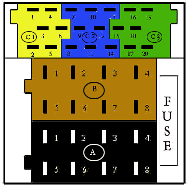
Then you use the mini iso (the yellow 6-pin called C1 in the figure below 

or a red 20-pin or a black 20-pin)

'97 Audi A4 Gamma stereo replace - Last Post -- posted image.

See the figure to make it easier to understand (the back of your Gamma headunit).

In the yellow connector:

Pin 1: Line out left rear

Pin 2: Line out right rear

Pin 3: Line out ground (common for all 4 channels)

Pin 4: Line out left front

Pin 5: Line out right front

Pin 6: Remote (common for all 4 individual speaker amps, not always used, sometimes

you use A3, equals pin 3 in the black 8-pin connector)

There should be a sticker on the Gamma headunit that explains all this to you.

In Sweden we use an adapter for about 53 usd that makes it so easier to install.

And also when we buy a new Hu its always end with a female ISO.

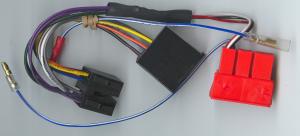
You could use this one:

'97 Audi A4 Gamma stereo replace - Last Post -- posted image.

This is Autoleads PC 9401 that fits several Audis.

There can be several to choose from depending on several things for example the voltage on the line out.

See http://www.autoleads.co.uk/installation_db.html for more info.

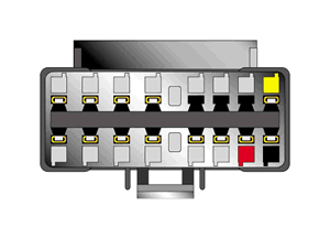
And if you dont want to cut any cables in your car you can look for an PC 3433 from the same

manufacturer. It will fit your Sony in one end and it has a female ISO in the other!

'97 Audi A4 Gamma stereo replace - Last Post -- posted image.

We have done that ourselves when our customers has bought a Sony from the U.S.

Or you can just buy a Hu from Blaupunkt, they use mini iso.

Good luck!

mmh1 
Copper - Posts: 117
Copper spacespace
Joined: May 10, 2005
Location: United Kingdom
Posted: October 28, 2006 at 6:58 AM / IP Logged  
Thank you very much for your help, I had almost given up on it.
I will try out you advice and let you know the result. The diagrams are a great help and I should be able to sort it out now.
Thanks,
M :)

Sorry, you can NOT post a reply.
This topic is closed.

  Printable version Printable version Post ReplyPost New Topic
You cannot post new topics in this forum
You cannot reply to topics in this forum
You cannot delete your posts in this forum
You cannot edit your posts in this forum
You cannot create polls in this forum
You cannot vote in polls in this forum

  •  
Search the12volt.com
Follow the12volt.com Follow the12volt.com on Facebook
Friday, May 3, 2024 • Copyright © 1999-2024 the12volt.com, All Rights Reserved Privacy Policy & Use of Cookies
Disclaimer: *All information on this site ( the12volt.com ) is provided "as is" without any warranty of any kind, either expressed or implied, including but not limited to fitness for a particular use. Any user assumes the entire risk as to the accuracy and use of this information. Please verify all wire colors and diagrams before applying any information.

Secured by Sectigo
the12volt.com spacer
Support the12volt.com
Top
the12volt.com spacer