the12volt.com spacer
icon

building enclosure, port location?


Post ReplyPost New Topic
< Prev Topic Next Topic >
bellsracer 
Silver - Posts: 703
Silver spacespace
Joined: January 14, 2006
Location: United States
Posted: September 20, 2006 at 1:08 AM / IP Logged  

Put the port on the same side as the subs in the middle. Computer programs (well most of them) won't tell you how the soundwaves will travel specifically but putting the port in the middle will achieve the best results on the reflecting waves in the enclosure. If you want to put the port on the side of the box, keep it as close to the side of the box as the subs to keep the imaging stable.

Then your next issue would be to control the reflected waves within the box. Sound absorbing materials (not sound dampening) lining the walls and the port (not on the inside of the port) will allow the side port to function at its best.

But for maximum effect, stick with the port in the middle. It's a known, proven system for big hits.

Good Luck!

Never send your ducks to eagle school.
The difference between ordinary and extraordinary is that little extra.
The 3Ls of life: Learn from the Past, Live for the Present, Look to the Future.
hemanjoyman 
Copper - Posts: 77
Copper spacespace
Joined: August 18, 2006
Location: United States
Posted: September 20, 2006 at 11:59 AM / IP Logged  
killersonata
I, like stevdart, would like to know how to go about tuning a cabinet with that particular design you mentioned. It seems like that might be the way I go.
building enclosure, port location? - Page 2 -- posted image.
bellsracer 
Silver - Posts: 703
Silver spacespace
Joined: January 14, 2006
Location: United States
Posted: September 20, 2006 at 8:30 PM / IP Logged  
nouseforaname wrote:
~snip~

bellsracer, why in the world would you line the inner walls with a sound absorbing material? i've never heard of that nor have i ever done it and my boxxes function just fine. and who proved the middle of the box is the best place for the port for "maximum effect"? the port can be on the top, bottom, either side, OR the middle, as long as the port fires in the same direction that the sub is facing, it doesn't matter.

It's an overkill thing. Pressure is the determining factor for getting sound out. but as much as 2 db can be gained by having the walls absorb the soundwaves instead of dampening them. When we analyzed various single chamber, dual sub, side port boxes this helps create a better munsen curve and gives the sound a cleaner exit to match the subs. It's a physics thing we played around with for one of our concept mini-cars.
Never send your ducks to eagle school.
The difference between ordinary and extraordinary is that little extra.
The 3Ls of life: Learn from the Past, Live for the Present, Look to the Future.
stevdart 
Platinum - Posts: 5,816
Platinum spaceThis member has made a donation to the12volt.com. Click here for more info.spaceThis member has been recognized as an authority in Mobile Audio and Video. Click here for more info.spaceThis member consistently provides reliable informationspace
Joined: January 24, 2004
Location: Pennsylvania, United States
Posted: September 20, 2006 at 9:13 PM / IP Logged  

bellsracer wrote:
this helps create a better munsen curve

bellsracer, let me get this straight:  you and your crew performed scientific testing on sub enclosures, at least one of which had the port on the front at the side, and at least one that had the port dead center between two subs.  And being a controlled test, both enclosures, bracing, drivers, power input, source material, etc. were identical.  Is this right so far?

So now, what is perplexing:

You said that you found a difference in Fletcher-Munsen curves between the two enclosures?

Build the box so that it performs well in the worst case scenario and, in return, it will reward you at all times.
bellsracer 
Silver - Posts: 703
Silver spacespace
Joined: January 14, 2006
Location: United States
Posted: September 21, 2006 at 11:50 AM / IP Logged  
stevdart wrote:
bellsracer, let me get this straight:  you and your crew performed scientific testing on sub enclosures, at least one of which had the port on the front at the side, and at least one that had the port dead center between two subs.  And being a controlled test, both enclosures, bracing, drivers, power input, source material, etc. were identical.  Is this right so far?

So now, what is perplexing:

You said that you found a difference in Fletcher-Munsen curves between the two enclosures?

Pretty much... D is one of those guys who love to refine things to perfection. Tek is like his no. 2 for these concept things.

When it came to power draw versus SQ for flatline, we found that during our test between 80-125 Hz @ 100 db the curve lifted slightly in order to match target spl properly.

After absorbing the sound, we found a 2 db increase in spl and had to drop the power a bit in order to match target spl. This was consistant with the calculations that Tek and D did to figure out what was happening to the soundwaves reflecting in the box.

To be honest I'm not 100% sure what the equations are or anything but I do remember seeing their book they filled with all the calculations. It was about 120 pages of calculations and 15 pages-ish of written notes.

Tek made us crossovers that bandpass the targeted tone with 24db/octave cuts +-2Hz from target. It was kind of strange and I don't understand it all myself, but that is their results.

I didn't think that the overkill deal would get this attention... It was more of a chindogu (useful but not practical idea)

As for the technology in the shop, most of our testing equipment is the same equipment used in SPL and SQ competitions. A Gateway (top notch) computer controls our sound test equipment. TPI 440s help us double check what the equipment is doing while installing and fabricating. It's nothing wow worthy so much as it is just used a lot.

Never send your ducks to eagle school.
The difference between ordinary and extraordinary is that little extra.
The 3Ls of life: Learn from the Past, Live for the Present, Look to the Future.
hemanjoyman 
Copper - Posts: 77
Copper spacespace
Joined: August 18, 2006
Location: United States
Posted: September 21, 2006 at 1:01 PM / IP Logged  
Well, does anyone know how to go about tuning with this type of port? How to account for the end correction factor, how to properly apply the length calculated since It cannot be done like a regular L-shaped port, since this is more like a T-shaped port?
L-shaped calculated like this for L1 and L2: building enclosure, port location? - Page 2 -- posted image.
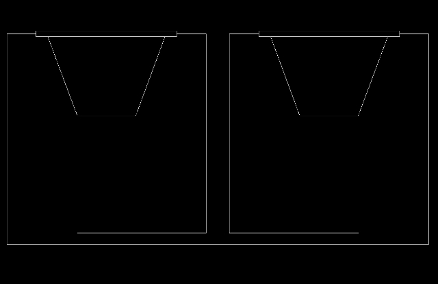
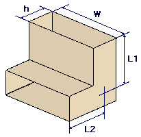
I'm assuming the T-shaped port would be L1, L2, and L3, but how do you go about taking the actual measurements of it?
stevdart 
Platinum - Posts: 5,816
Platinum spaceThis member has made a donation to the12volt.com. Click here for more info.spaceThis member has been recognized as an authority in Mobile Audio and Video. Click here for more info.spaceThis member consistently provides reliable informationspace
Joined: January 24, 2004
Location: Pennsylvania, United States
Posted: September 21, 2006 at 8:25 PM / IP Logged  
The box is already divided into two chambers with that design.  Just put one thin piece of wood down the center to separate the ports and be done with it.  Each sub will have its own port and you'll be able to model without all the guessing.
Build the box so that it performs well in the worst case scenario and, in return, it will reward you at all times.
hemanjoyman 
Copper - Posts: 77
Copper spacespace
Joined: August 18, 2006
Location: United States
Posted: September 22, 2006 at 11:51 AM / IP Logged  
I figured out how to design that type of port. beerman over at deCaf: Car Audio Forums helped me out with it.
building enclosure, port location? - Page 2 -- posted image.
hemanjoyman 
Copper - Posts: 77
Copper spacespace
Joined: August 18, 2006
Location: United States
Posted: September 22, 2006 at 11:52 AM / IP Logged  
This is the discussion we had about it:
http://www.subwoofertools.com/forum/topic.asp?TOPIC_ID=1003
Page of 2

Sorry, you can NOT post a reply.
This topic is closed.

  Printable version Printable version Post ReplyPost New Topic
You cannot post new topics in this forum
You cannot reply to topics in this forum
You cannot delete your posts in this forum
You cannot edit your posts in this forum
You cannot create polls in this forum
You cannot vote in polls in this forum

  •  
Search the12volt.com
Follow the12volt.com Follow the12volt.com on Facebook
Thursday, April 18, 2024 • Copyright © 1999-2024 the12volt.com, All Rights Reserved Privacy Policy & Use of Cookies
Disclaimer: *All information on this site ( the12volt.com ) is provided "as is" without any warranty of any kind, either expressed or implied, including but not limited to fitness for a particular use. Any user assumes the entire risk as to the accuracy and use of this information. Please verify all wire colors and diagrams before applying any information.

Secured by Sectigo
the12volt.com spacer
Support the12volt.com
Top
the12volt.com spacer