the12volt.com spacer
icon

custom led circuit in car


Post ReplyPost New Topic
< Prev Topic Next Topic >
implodejl 
Member - Posts: 10
Member spacespace
Joined: March 09, 2007
Location: United States
Posted: March 09, 2007 at 11:32 PM / IP Logged  

Found this site and forum very helpful but I have a question or maybe two.

I just went to the local electronics surplus store and boughts some LEDs. They weren't packaged or anything special. There wasn't any voltage or specs listed on these though. They shine yellow with green plastic (some are square heads, others are the standard round head). I tried to do some research and I'm getting that they are 2.2v LEDs, but still not 100% sure. I'm going to be making an "LED Tube" to light up the feet area under the glovebox and stearing wheel.

This is what I'm planning on having done. In theory it seems it would work but I'm not an expert at this stuff.

custom led circuit in car - Last Post -- posted image.

I also am pretty sure I need to put a fuse somewhere by the battery but I'm not sure what kind of fuse.

My questions:

1. Will this setup work?

2. Is there special wire I need to purchase since i'm connecting it to the car's battery

3. Since these LEDs are wired parallel, will this drain my car battery? I currently have two 12" subs hooked on a 770 watt amp hooked up to the battery as well.

Is there a better way to do this w/out buying kits

master5 
Silver - Posts: 1,123
Silver spacespace
Joined: October 10, 2006
Location: United States
Posted: March 10, 2007 at 3:40 PM / IP Logged  

First off...NOTHING you install in the vehicle should kill the battery...unless you do something wrong. If you wire the leds wrong..they will either be too dull (not enough voltage) or burn out fast (too much volage). Either way as long as you do not leave them on when the vehicle is not running..it will not do anything to the battery. Remember that once the vehicle is running..everything electrical is actually a load on the alternator..including the battery..which is being charged during that time.

There is no "special" wire used to connect to the battery..but all wire you install with should be oxygen free multi strand copper for the most reliability.and of the proper gauge to handle the current demands of what you connect to it..However, any conductor will allow current flow.

Just make sure anything you connect directly to the battery is fused close to the battery...the purpose of that fuse is to protect the wire in case of a short..without that fuse in the event of a short..the wire will burn..and depending on the size..can burn for some time..not a good scenerio.

The image you posted did not come out but regardless..if you are not 100% sure of the LED's voltage and current rating...no one could possibly help with any degree of accuracy.

Post back what you find about the values and the image if possible.

Take care.

implodejl 
Member - Posts: 10
Member spacespace
Joined: March 09, 2007
Location: United States
Posted: March 10, 2007 at 10:22 PM / IP Logged  

thank you for the reply, master 5.

https://i99.photobucket.com/albums/l289/tom44vip/LEDS.jpg?t=1173505230

this is the diagram I'm using. Is there a certain name for this specific fuse I need to buy?

I was also wondering if there is a way to test these LEDs maybe to a battery pack to see what voltage they require. I will keep trying to find this information, otherwise I should be all set.

Thanks again for your replies, your experience and knowledge on this subject is a tremendous help for specifics for someone like me (learning.)

tom

frydchkn 
Copper - Posts: 60
Copper spacespace
Joined: March 11, 2006
Location: United States
Posted: March 11, 2007 at 1:18 AM / IP Logged  

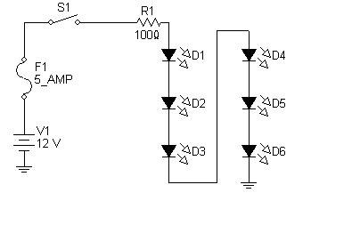
Your lights should be in series, not parallel like in your diagram.  Doing so will shoot 12V through, what you think are, your 2.2V lights.  6 in a row with a 100ohm resistor adds up to 13.2 volts

implodejl 
Member - Posts: 10
Member spacespace
Joined: March 09, 2007
Location: United States
Posted: March 11, 2007 at 11:36 PM / IP Logged  

Okay, I haven't made new diagrams yet, but by wiring them up in a series, I'll need to buy and attach resistors to each LED.  For my scenario, what color resistors should I use. And also, by wiring them in a Series, wouldn't that mess the battery up even more? I'm wiring these into my Car.

Can my car battery support the two subwoofers and aprox. 45 LEDs?

I'm gonna say that these are most likely 2.2v LEDs because I just wired them up to two AA batteries = 3v. and they worked perfectly.

frydchkn 
Copper - Posts: 60
Copper spacespace
Joined: March 11, 2006
Location: United States
Posted: March 12, 2007 at 12:34 AM / IP Logged  

Thats one resistor for each string of 6 lights in series.  I believe the colors are brown-black-black, double check that in the resistor basics section.  

LED's are very efficient, so 45 LEDs is not much of a load, I would check the current draw from a single LED with your two battery test.  Multiply this number by 6 (# of LEDs) and this will give you the total current (amperage) of a single string.

implodejl 
Member - Posts: 10
Member spacespace
Joined: March 09, 2007
Location: United States
Posted: March 16, 2007 at 1:07 PM / IP Logged  
thanks. just to confirm. I wire each set in a series and calculate the amount of amperage it requires then put in one resistor at the front. this resistor is the car battery minus the string.
fakepete 
Copper - Posts: 99
Copper spacespace
Joined: April 21, 2002
Location: United States
Posted: March 16, 2007 at 8:52 PM / IP Logged  
This is what frydchkn is describing. More LED/resistor strings could be added to this as necessary.
custom led circuit in car - Last Post -- posted image.
allan_uk 
Member - Posts: 1
Member spacespace
Joined: March 20, 2007
Location: United Kingdom
Posted: March 20, 2007 at 7:11 AM / IP Logged  
The current flowing through a string of six LEDs in series is the current of one LED - if the LEDs are 2V/20mA, the required current for the six LEDs in series is 20mA, but the voltage is 12V.
If they were in parallel, the current required would be 120mA, but the voltage would be 2V.
The power of one LED is 2 x 0.02 = 0.04W, so six would be 0.24W, which is 2V x 120mA OR 12V x 20mA.
Hope that makes sense!
The problem with driving LEDs in series is if one is not 'balanced' with the others - the current drawn by an LED is dependant on the voltage it sees and vice versa, so a string of six LEDs may see one dropping 2.1V, another 1.9V.
Normally this is not a problem, as the difference in brightness is normally not noticeable, the problem arises if the one LED that sees 2.1V is not happy at that voltage and overheats. You then have no LEDs working as the circuit is broken.
It may not cause a problem, just something to be aware of.

Sorry, you can NOT post a reply.
This topic is closed.

  Printable version Printable version Post ReplyPost New Topic
You cannot post new topics in this forum
You cannot reply to topics in this forum
You cannot delete your posts in this forum
You cannot edit your posts in this forum
You cannot create polls in this forum
You cannot vote in polls in this forum

  •  
Search the12volt.com
Follow the12volt.com Follow the12volt.com on Facebook
Thursday, April 25, 2024 • Copyright © 1999-2024 the12volt.com, All Rights Reserved Privacy Policy & Use of Cookies
Disclaimer: *All information on this site ( the12volt.com ) is provided "as is" without any warranty of any kind, either expressed or implied, including but not limited to fitness for a particular use. Any user assumes the entire risk as to the accuracy and use of this information. Please verify all wire colors and diagrams before applying any information.

Secured by Sectigo
the12volt.com spacer
Support the12volt.com
Top
the12volt.com spacer