the12volt.com spacer
icon

air horn circuit diagram is it correct?


Post ReplyPost New Topic
< Prev Topic Next Topic >
iblis 
Member - Posts: 19
Member spacespace
Joined: April 06, 2006
Location: Ireland
Posted: April 20, 2007 at 10:17 AM / IP Logged  

Hi all,

I've drawn up a circuit diagram before installing my electric air horn. I've drawn my modifications (in red) onto the car's wiring diagrams. Does my approach make sense? Is there anything missing/unnecessary?

Sorry bit of an electrical newbie. The idea of the switch marked with the big black arrow is: when open, only stock horn responds to pressing the horn button; when closed, both respond.

Thanks in advance!

http://mr2oc.co.uk/modules/coppermine/albums/userpics/14067/nautilus.gif

iblis 
Member - Posts: 19
Member spacespace
Joined: April 06, 2006
Location: Ireland
Posted: April 20, 2007 at 10:27 AM / IP Logged  
That earth to the right of the relay shouldn't be there... I was sure I erased it!   air horn circuit diagram is it correct? -- posted image.
iblis 
Member - Posts: 19
Member spacespace
Joined: April 06, 2006
Location: Ireland
Posted: April 20, 2007 at 10:30 AM / IP Logged  

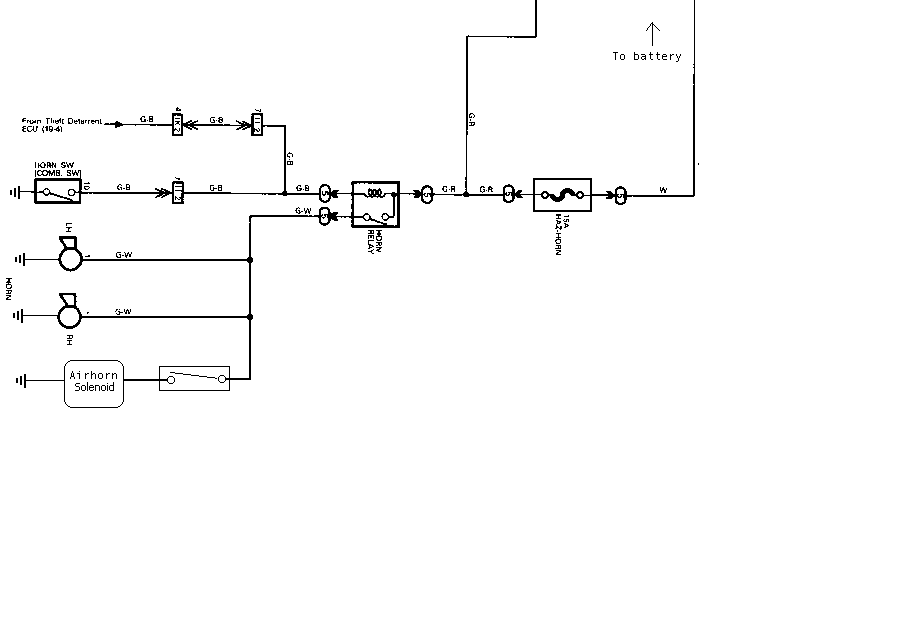
"Correct" diagram below:

http://mr2oc.co.uk/modules/coppermine/albums/userpics/14067/nautilus2.gif

hotwaterwizard 
Silver - Posts: 1,350
Silver spacespace
Joined: December 11, 2003
Location: California, United States
Posted: April 21, 2007 at 5:44 PM / IP Logged  

Please Explain why you need a Relay. ????>??????

An air horn Solinoid uses about the same current as the Relay. Why do you need a Relay. You only need a Relay for a Regular horn.

air horn circuit diagram is it correct? -- posted image.

John DeRosa (Hotwaterwizard)
Stockton California
When in doubt, try it out !
hotwaterwizard 
Silver - Posts: 1,350
Silver spacespace
Joined: December 11, 2003
Location: California, United States
Posted: April 21, 2007 at 6:06 PM / IP Logged  

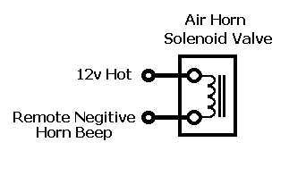
Here is a simpler diagram.

air horn circuit diagram is it correct? -- posted image.

John DeRosa (Hotwaterwizard)
Stockton California
When in doubt, try it out !
hotwaterwizard 
Silver - Posts: 1,350
Silver spacespace
Joined: December 11, 2003
Location: California, United States
Posted: April 21, 2007 at 6:43 PM / IP Logged  

Keep it Simple.

Less problems that way.

John DeRosa (Hotwaterwizard)
Stockton California
When in doubt, try it out !
hotwaterwizard 
Silver - Posts: 1,350
Silver spacespace
Joined: December 11, 2003
Location: California, United States
Posted: April 21, 2007 at 6:51 PM / IP Logged  

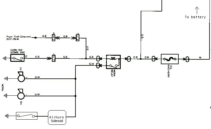
Even Better!

air horn circuit diagram is it correct? -- posted image.

John DeRosa (Hotwaterwizard)
Stockton California
When in doubt, try it out !
dualsport 
Silver - Posts: 983
Silver spacespace
Joined: September 27, 2005
Location: United States
Posted: April 21, 2007 at 7:52 PM / IP Logged  
If the air horn shown in the original diagram is the actual compressor and not a relay, then it does draw a lot of current, so that may be why the separate 20A fused circuit was added to supply the air horn.
In any case, the control for the air horn has to come from the right side of the horn connections, like Hotwaterwizard shows, because the other side is grounded. Adding that diode in line with the RH horn will do nothing; though it might seem like the current flows that way and you could tap off the signal from the diode output, it doesn't work that way. Once it hits ground, it's ground.
If the box shown for the air horn is supposed to just be a separate relay controlling the air horn compressor, then simply wire it as shown by Hotwaterwizard; if not, then just add a relay. No need for any diodes, because you're not dealing with any electronic drive circuitry and don't need to isolate anything.
iblis 
Member - Posts: 19
Member spacespace
Joined: April 06, 2006
Location: Ireland
Posted: April 22, 2007 at 6:50 AM / IP Logged  
Hi all,
Thanks for all the replies! As above, I'm not very experienced with this stuff, so apologies if any of the below is crazy talk air horn circuit diagram is it correct? -- posted image.
The airhorn box is an electric compressor (should have been clearer about that). The switch is to go in the cabin, so I figured the relay would be a good idea rather than wiring higher gauge cable all the way through to the cabin.
I'm not sure if the existing horn wiring is high enough gauge to safely carry the compressor's current, so that's why I put a seperate 20A fused feed.
Are either of those correct?
Thanks again.
dualsport 
Silver - Posts: 983
Silver spacespace
Joined: September 27, 2005
Location: United States
Posted: April 22, 2007 at 8:06 AM / IP Logged  
This should be all you have to do-
https://img293.imageshack.us/img293/3449/aircompressorcntldx0.jpg
diagram
Page of 2

  Printable version Printable version Post ReplyPost New Topic
You cannot post new topics in this forum
You cannot reply to topics in this forum
You cannot delete your posts in this forum
You cannot edit your posts in this forum
You cannot create polls in this forum
You cannot vote in polls in this forum

  •  
Search the12volt.com
Follow the12volt.com Follow the12volt.com on Facebook
Wednesday, April 17, 2024 • Copyright © 1999-2024 the12volt.com, All Rights Reserved Privacy Policy & Use of Cookies
Disclaimer: *All information on this site ( the12volt.com ) is provided "as is" without any warranty of any kind, either expressed or implied, including but not limited to fitness for a particular use. Any user assumes the entire risk as to the accuracy and use of this information. Please verify all wire colors and diagrams before applying any information.

Secured by Sectigo
the12volt.com spacer
Support the12volt.com
Top
the12volt.com spacer