the12volt.com spacer
icon

radio on till door opens


Post ReplyPost New Topic
< Prev Topic Next Topic >
mrcanngo 
Copper - Posts: 63
Copper spacespace
Joined: March 17, 2007
Posted: October 13, 2007 at 2:10 AM / IP Logged  
These questions actually pertain to a car with a negative door trigger but i thought i'd post here to keep things cleaner. anyways:
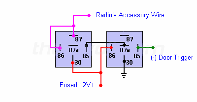
As per the diagram here: https://www.the12volt.com/relays/page5.asp#drto
under "Radio on until door opened"
There is something i dont understand. Please note, i'm sure that this works but i just wanted to clear some confusion i had.
On the left Relay here are my questions:
1.) I see that 87 and 86 are both connected to Radio accesory, does this mean just directly to the stereo's acc wire? No connection is made to the vehicles acc?
2.) If so, when the car is off or on for that matter, doesn't that mean that 86 is not being powered by anything at all? Maybe i don't know what the ACC wire on a stereo is supposed to be used for, but i thought that when the stereo gets +12v on the ACC line, it knows to power the stereo. (and when it loses it, to turn it off) right?
3.) if 86 is not being powered and 85 is just ground, then that means that the relay is NOT energized therefore 30 and 87a have continuity, doesn't this make the relay useless? Since 30 is just going to give +12v to 87a which is connected to nothing.
The only way i can understand this relay making any sense is if the RADIO GAVE +12V on the ACC line instead of receiving it. Please correct me if i'm wrong here.
the12volt 
Administrator - Posts: 3,955
Administrator spaceThis member has made a donation to the12volt.com. Click here for more info.spaceThis member has been recognized as an authority in Electrical Theory. Click here for more info.spaceThis member has been recognized as an authority in Mobile Audio and Video. Click here for more info.spaceThis member has been recognized as an authority in Mobile Security and Convenience. Click here for more info.spacespace
Joined: March 07, 2002
Location: Louisiana, United States
Posted: October 13, 2007 at 8:14 AM / IP Logged  

The radio accessory wire and the vehicle accessory wire are the same in the first diagram. As soon as terminal 86 of the left relay is provided with 12V+, terminals 86, 87 and 30 will have continuity. Since terminal 30 is connected to a constant 12V+, terminals 86 and 87 will always show 12V+ until this latch is broken by removing ground from terminal 85 (done by the relay on the right when a door is opened) or you could remove 12V+ from terminal 30 of the relay on the left. 

radio on till door opens - Last Post -- posted image.

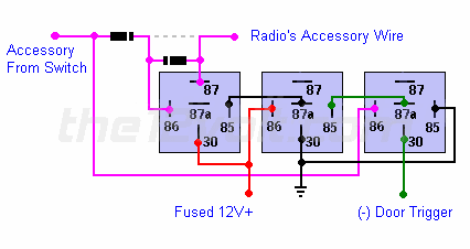
If you intend to use relays to add this feature, I'd recommend using my second diagram.

radio on till door opens - Last Post -- posted image.

radio on till door opens - Last Post -- posted image. the12volt • Support the12volt.com
mrcanngo 
Copper - Posts: 63
Copper spacespace
Joined: March 17, 2007
Posted: October 15, 2007 at 9:34 PM / IP Logged  
Is it dangerous doing the first way? I have only 2 relays right now but i'll go get another if the second one is a lot better.
could u please explain why the second method is better?
07mustanggt 
Copper - Posts: 89
Copper spacespace
Joined: October 02, 2007
Posted: October 23, 2007 at 10:15 PM / IP Logged  
So what does the relay set up do. I have a 07 mustang, and my radio stays on until a door is open, which is kinda cool. Does this set up turn the radio off when the key is removed or what?
mrcanngo 
Copper - Posts: 63
Copper spacespace
Joined: March 17, 2007
Posted: October 24, 2007 at 2:39 AM / IP Logged  
actually, i'm trying to get my car to be like yours. I have an 06 mazda3 that i want to have my stereo keep playing until i open my door with the key out of the barrel.
I wanted to add a timer function on this as well just in case but no idea how to. Any suggestions?
tbird2340 
Copper - Posts: 363
Copper spacespace
Joined: October 03, 2003
Location: Ohio, United States
Posted: October 26, 2007 at 8:29 AM / IP Logged  
I am actually trying to get the hang of relays and how they work and just looked at this sample yesterday. Here is what I got:
Relay 2 on the right has pin 87a being ground when the coil isn’t charged. 87a is connected to one side of the coil on relay 1 so with the car off, relay 1 pin 85 is at ground. When the vehicle turns on the accessory wire gets 12V which powers relay one (completes the coil circuit as 85 is ground). With relay one energized the constant 12v on pin 30 of relay 1 connects to pin 87 of relay 1 which is also the accessory wire. Relay 2 is still not energized at this time.. The person turns the vehicle off but since the constant 12V is now connected to the accessory wire through the relay the radio stays on…
When the door gets opened a ground gets sent to pin 85 of relay 2 energizing relay 2. This REMOVES ground from 87a which is how relay 1 is getting energized thus removing the constant 12V from the accessory wire..
When the door is then closed the coil on relay 2 is not energized anymore which puts 87a back to ground but since the accessory wire has lost its constant 12v relay 1 will not be repowered until the vehicle is started again..
That is my uneducated explanation..

Sorry, you can NOT post a reply.
This topic is closed.

  Printable version Printable version Post ReplyPost New Topic
You cannot post new topics in this forum
You cannot reply to topics in this forum
You cannot delete your posts in this forum
You cannot edit your posts in this forum
You cannot create polls in this forum
You cannot vote in polls in this forum

  •  
Search the12volt.com
Follow the12volt.com Follow the12volt.com on Facebook
Saturday, May 4, 2024 • Copyright © 1999-2024 the12volt.com, All Rights Reserved Privacy Policy & Use of Cookies
Disclaimer: *All information on this site ( the12volt.com ) is provided "as is" without any warranty of any kind, either expressed or implied, including but not limited to fitness for a particular use. Any user assumes the entire risk as to the accuracy and use of this information. Please verify all wire colors and diagrams before applying any information.

Secured by Sectigo
the12volt.com spacer
Support the12volt.com
Top
the12volt.com spacer