


Posted: February 19, 2014 at 8:19 PM / IP Logged


Posted: February 20, 2014 at 5:46 AM / IP Logged
Posted: February 20, 2014 at 9:50 AM / IP Logged
Posted: February 20, 2014 at 10:10 AM / IP Logged
Posted: February 20, 2014 at 10:53 AM / IP Logged
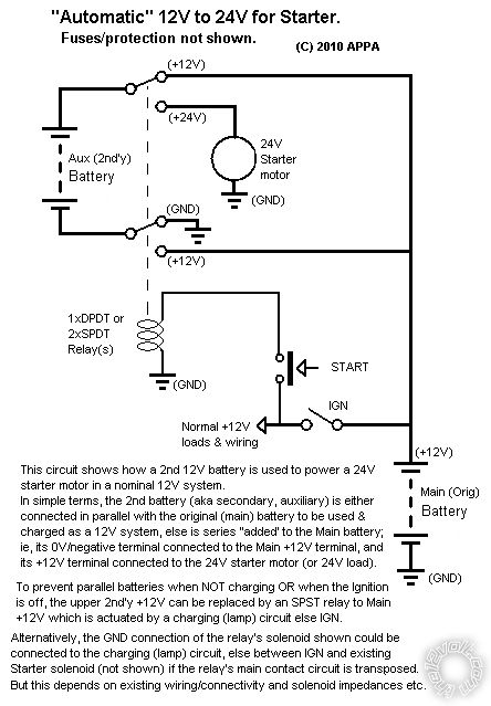 With the relay energised (IGN & Start closed), the top relay arm swings down to the 24V starter motor and the bottom arm reconnects the "upper" battery's -ve to +12V, hence making the upper battery's +ve terminal (12 + 12 =) 24V.
At no time does the lower 12V part see 24V, it only ever sees the lower battery's 12V.
If however the lower arm connects to +12V BEFORE the upper contact has broken it's upper contact, you then have a short across the upper 12V battery.
That's the failsafe part - if using TWO SPDT relays (or several SPST) instead of a DPDT relay, you must ensure the upper arm breaks from the upper contact before the lower arm makes its lower contact.
Of course all you have to do is pair up 2 batteries in parallel for your Main and Aux/secondary batteries respectively and connect according to that diagram.
However I am so conditioned into NOT having paralleled batteries (except when being used or when being charged) that I automatically think of (automatic) battery isolation and that's what I mention in the diagram's notes.
But that fig was for ONE extra battery added to the Main battery for a 24V starter.
I'd assume your 4 batteries are separate to your main battery, hence for isolation four isolating relays are required else 4 terminals need to be disconnected (IMO after a few or several hours if leaving unused or not charging).
With the relay energised (IGN & Start closed), the top relay arm swings down to the 24V starter motor and the bottom arm reconnects the "upper" battery's -ve to +12V, hence making the upper battery's +ve terminal (12 + 12 =) 24V.
At no time does the lower 12V part see 24V, it only ever sees the lower battery's 12V.
If however the lower arm connects to +12V BEFORE the upper contact has broken it's upper contact, you then have a short across the upper 12V battery.
That's the failsafe part - if using TWO SPDT relays (or several SPST) instead of a DPDT relay, you must ensure the upper arm breaks from the upper contact before the lower arm makes its lower contact.
Of course all you have to do is pair up 2 batteries in parallel for your Main and Aux/secondary batteries respectively and connect according to that diagram.
However I am so conditioned into NOT having paralleled batteries (except when being used or when being charged) that I automatically think of (automatic) battery isolation and that's what I mention in the diagram's notes.
But that fig was for ONE extra battery added to the Main battery for a 24V starter.
I'd assume your 4 batteries are separate to your main battery, hence for isolation four isolating relays are required else 4 terminals need to be disconnected (IMO after a few or several hours if leaving unused or not charging).Sorry, you can NOT post a reply.
This topic is closed.
 Printable version
| You cannot post new topics in this forum You cannot reply to topics in this forum You cannot delete your posts in this forum You cannot edit your posts in this forum You cannot create polls in this forum You cannot vote in polls in this forum |

| Search the12volt.com |
Follow the12volt.com 
Tuesday, May 12, 2026 • Copyright © 1999-2026 the12volt.com, All Rights Reserved • Privacy Policy & Use of Cookies

Tuesday, May 12, 2026 • Copyright © 1999-2026 the12volt.com, All Rights Reserved • Privacy Policy & Use of Cookies
Disclaimer:
*All information on this site ( the12volt.com ) is provided "as is" without any warranty of any kind, either expressed or implied, including but not limited to fitness for a particular use. Any user assumes the entire risk as to the accuracy and use of this information. Please
verify all wire colors and diagrams before applying any information.
