Posted: March 08, 2011 at 10:45 PM / IP Logged
Posted: March 09, 2011 at 12:52 AM / IP Logged
Posted: March 10, 2011 at 2:18 AM / IP Logged
Posted: March 10, 2011 at 3:32 AM / IP Logged
Posted: March 12, 2011 at 1:37 PM / IP Logged
Posted: March 13, 2011 at 6:27 AM / IP Logged
Sorry, you can NOT post a reply.
This topic is closed.
 Printable version


| You cannot post new topics in this forum You cannot reply to topics in this forum You cannot delete your posts in this forum You cannot edit your posts in this forum You cannot create polls in this forum You cannot vote in polls in this forum |

| Search the12volt.com |
Follow the12volt.com 
Monday, February 2, 2026 • Copyright © 1999-2026 the12volt.com, All Rights Reserved • Privacy Policy & Use of Cookies


Monday, February 2, 2026 • Copyright © 1999-2026 the12volt.com, All Rights Reserved • Privacy Policy & Use of Cookies
Disclaimer:
*All information on this site ( the12volt.com ) is provided "as is" without any warranty of any kind, either expressed or implied, including but not limited to fitness for a particular use. Any user assumes the entire risk as to the accuracy and use of this information. Please
verify all wire colors and diagrams before applying any information.


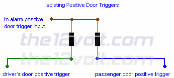
 ...where the Kathode = line-end "to alarm positive door trigger input" is to your door switch (ie Courtesy Lamps Switch, or Door Ajar Switches if appropriate)...
..and the other ends are: one to the normal car circuit, and one to #85 of the relay (#86 being to +12V).
Keep in mind current in a diode can flow from Anode to Cathode = Anode "in the direction of the arrow" and out the Cathode where the Cathode is the line end (aka brick wall end - current hits the wall if it comes in that end).
The arrow refers to the circuit symbol --->|--- ie, A-->|--K where we use K for Kathode because it's the mirror image diode symbol to above - ie, K--K--A.
Apologies - I thought I had a good door-switch and other stuff via diodes diagram in another thread, but I can't find it....
[ FYI - The above is not the reason for the K=Cathode, but it's the reason I'm giving because I find it easy to remember the "arrow" symbol, hence I can work out the direction of current flow +ve to -ve in the direction of the arrow.
The rest is easy....
Viz: the line end of the K or arrow --|<-- is the line end of the actual diode.
And if the line-end is is the K end, the other end must be the Anode.
And since it is +ve to -ve thru the arrow - ie, +ve into Anode & -ve at the K/Cathode, I sound as if I know something despite the fact that I never really remember whether anodes are +ve or -ve.
That's what I call "from first principles" (which is how people like me with limited memory work or survive!). ]