


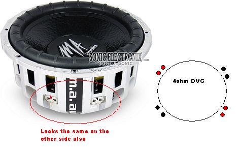
How to wire two 4 ohm DVC subs


Posted: December 06, 2006 at 5:11 PM / IP Logged


Posted: December 06, 2006 at 8:48 PM / IP Logged
Posted: December 07, 2006 at 7:49 AM / IP Logged


Posted: December 07, 2006 at 8:07 AM / IP Logged
 the12volt

Posted: December 07, 2006 at 9:24 PM / IP Logged
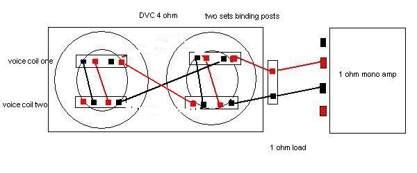 Look at the voice coil on the left sub labeled "voice coil one". I put a block around the two sets of input posts to make it simpler to see that although there are two sets of posts, it is still just one voice coil. The two positives are connected together (internally); the two negatives are connected together likewise.
The result of the above wiring is: coils parallel / subs parallel. The extra terminal inputs are used to connect a voice coil to another voice coil without having to put two wires onto one terminal post. You can see here that not all inputs have to be used, but that every coil is connected.
Look at the voice coil on the left sub labeled "voice coil one". I put a block around the two sets of input posts to make it simpler to see that although there are two sets of posts, it is still just one voice coil. The two positives are connected together (internally); the two negatives are connected together likewise.
The result of the above wiring is: coils parallel / subs parallel. The extra terminal inputs are used to connect a voice coil to another voice coil without having to put two wires onto one terminal post. You can see here that not all inputs have to be used, but that every coil is connected.Posted: December 11, 2006 at 7:48 PM / IP Logged
Sorry, you can NOT post a reply.
This topic is closed.
 Printable version
| You cannot post new topics in this forum You cannot reply to topics in this forum You cannot delete your posts in this forum You cannot edit your posts in this forum You cannot create polls in this forum You cannot vote in polls in this forum |

| Search the12volt.com |
Follow the12volt.com 
Saturday, April 4, 2026 • Copyright © 1999-2026 the12volt.com, All Rights Reserved • Privacy Policy & Use of Cookies

Saturday, April 4, 2026 • Copyright © 1999-2026 the12volt.com, All Rights Reserved • Privacy Policy & Use of Cookies
Disclaimer:
*All information on this site ( the12volt.com ) is provided "as is" without any warranty of any kind, either expressed or implied, including but not limited to fitness for a particular use. Any user assumes the entire risk as to the accuracy and use of this information. Please
verify all wire colors and diagrams before applying any information.
