This is a basic remote start with keyless entry Pictorial on a 2005 Buick Century. The 2000 through 2005 models should be
the same. These vehicles had the VATS anti-theft system ( resistor chip on key ), "one touch" starting and built in anti-grind.
Very straight-forward vehicle to install an after-market R/S system in to.
If the installer had the desire, you could do this install without a bypass module. The VATS system could be bypassed
during a remote start by obtaining a Directed 652T VATS resistor kit ( > $5 ), a relay ( > $4 ) and following this diagram :
https://www.the12volt.com/installbay/file.asp?ID=237 Everything else could be hardwired. ( Pictures at end )
I chose to use a bypass module for the extra features it provides and the simplicity of the install. There are many good
bypass modules available but for the DIY'er the Fortin INT-SL or INT-SL+ ( XPressKit DLPKGM ) or the iDatalink
ADS DLSL GM1+ are the best choices, as they come pre-loaded with firmware and are ready to go right out of the box.
Any quality remote start w/keyless entry system can be used. Due to the vehicles many ignition circuits ( 2 IGN's and
2 ACC's ) additional parts ( 30/40 Amp SPDT relay, in-line fuse holder and 25 Amp fuse ) will be required.
Below is the wiring when using a Compustar CS800-s remote start unit and a Fortin INT-SL+ bypass module :
CS800-s
CN1
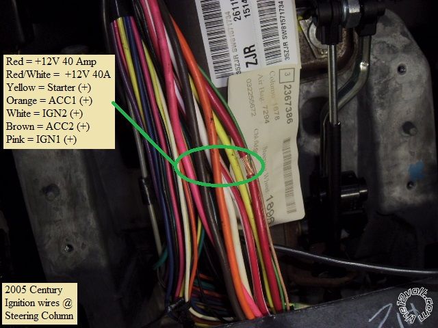
1 Red +12V Constant Century Red @ main ignition harness
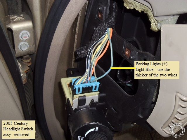
2 GREEN / WHITE + Parking Light Out Century Light Blue at headlight switch
3 RED / White +12V Constant Century RED / White @ main ignition harness
4 White + Accessory Century Orange @ main ignition harness
5 Blue + Selectable * Set to IGN2 Century White @ main ignition harness
6 Yellow + Starter Century Yellow @ main ignition harness
7 Green + Ignition Century Pink @ main ignition harness
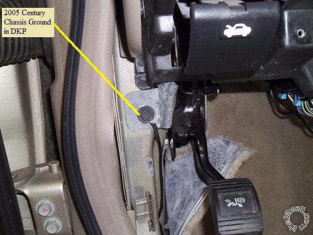
8 Black Chassis Ground Century frame bolt
CN2
1 GREEN / WHITE (-) Parking Lights Not Used
2 RED / Black (-) Starter Not Used
3 WHITE/ Black (-) Accessory to extra relay Pin 85
4 Black (-) Status to INT-ST+ Blue wire
5 Orange (-) Rearm Not Used
6 ORANGE / White (-) Disarm Not Used
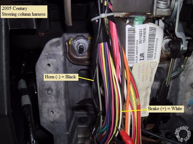
7 White (-) Horn Century Black @ steering column harness
8 Gray/Black (-) Hood Pin to CS800-s kit supplied hood pin
9 Lt Blue/White (+) Brake Century White @ steering column harness
10 RED / White (-) Trigger Start Not Used
11 Red (+) Trigger Start Not Used
12 Yellow/Black Tach to INT-SL+ ORANGE / Black wire
CN3
1 Empty
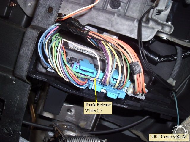
2 Violet/White (-) Trunk Release to INT-SL+ Light Blue/Black wire
3 ORANGE / Black (-) Driver Priority Unlock Not Used
4 Blue (-) Unlock to INT-SL+ White wire
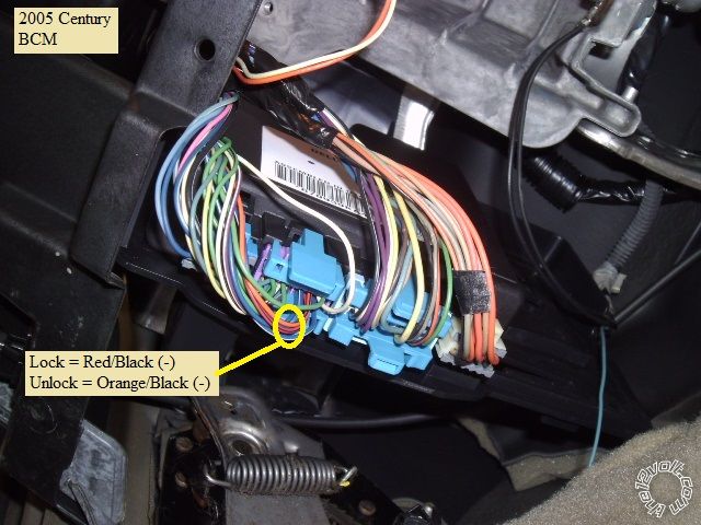
5 Blue/Black (-) Lock to INT-SL+ Light Blue
6 Empty
Extra 30/40 Amp Relay for Accessory2
Relay Pin 85 to CS800-s CN2 Pin 3 WHITE/ Black
Relay Pin 86 and 87 to Century RED / White @ main ignition harness through 25 amp fuse
Relay Pin 30 to Century Brown @ main ignition harness
Relay Pin 87a not used
Fortin INT-SL+ ( W2W mode )
4 Pin plug ( cut off one end )
Red to CS800-s CN1 Pin 1 Red
Black to CS800-s CN1 Pin 8 Black
14 Pin Plug
Light Blue to CS800-2 CN3 Pin 5 Blue/Black
Light Blue/Black to CS800-s CN3 Pin 2 Violet/White
White to CS800-s CN3 Pin 4 Blue
WHITE/ Black not used
Pink to CS800-s CN1 Pin 7 Green
Pink/Black not used / supported
Blue to CS800-s CN2 Pin 4 Black
Green not used
Orange not used / supported
ORANGE / Black not used
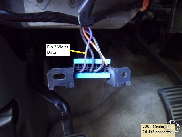
Purple to Century OBD2 connector Pin 2 Violet
PURPLE / White not used / supported
Yellow not used / supported
Yellow/Black not used / supported
Vehicle disassembly :
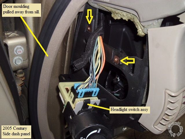
Pull the door molding away from the car in the lower driver kick panel area and up to the door window. Remove the
driver side panel and driver kick panel.
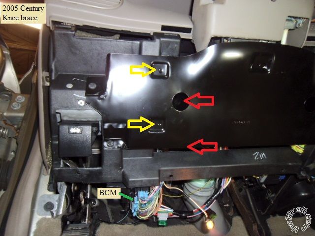
Remove the 2 plastic fasteners that retain the under dash insulation panel and remove the insulation panel.
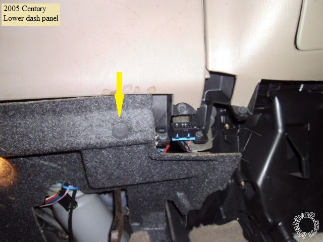
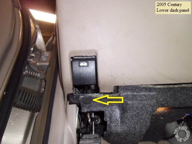
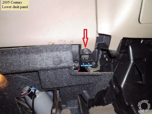
Remove the one Phillips screw by the OBD2 connector and pull the lower dash panel away from the dash and remove.

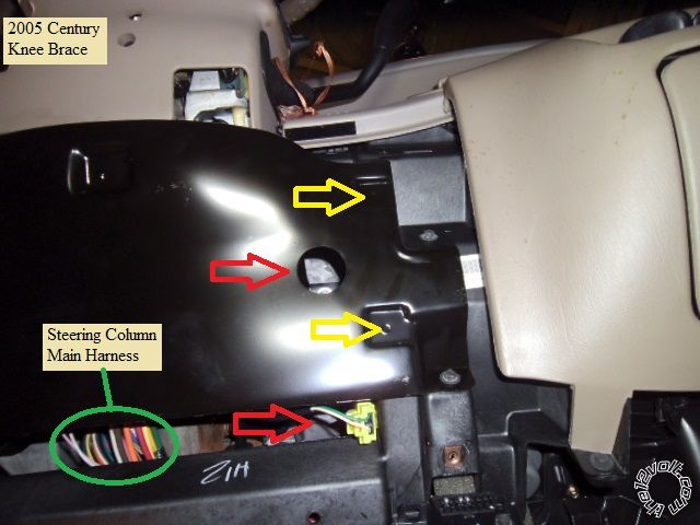
The knee brace plate is held in place by 4 Phillips screws ( marked with yellow arrows ) and four recessed 10mm bolts ( marked with
red arrows - use a deep socket ). Remove this plate for full access to the steering column and main ignition harness.
At the side of the dash, remove the two Phillips screws that retain the headlight switch assy ( yellow arrows ), pull the back
end of the switch out and push the switch out of the dash.
Wiring :
This is a photo of the main ignition harness :
Next is a photo the Brake and Horn wires in the steering column harness :
This is a picture of a suitable chassis ground wire location ( there are other good locations ) :
Here is a photo of the Parking Light wire :
While several wire guide listings show a (-) Parking Light wire at the BCM, a Gray/Black wire in either the Purple or Blue
connector, I could not locate and verify this wire on this car.
The OBD2 connector was shown in this photo ( just under the marked screw ) :
And here is the back side of the OBD2 plug with the Violet wire at Pin 2 marked :
In case you wish to do the VATS bypass more directly / permanently, you can also delete the bypass module and hardwire
the door locks and trunk release. These wires are located in the BCM Purple connector and are shown below :
Firewall pass through for the hood pin wire can be found at the grommet for the hood release cable.
As mentioned above, the car has "one-touch" starting and built-in anti-grind. While the bypass module supplies a
Tach signal, you could set the remote starter to go Tachless or just output a fixed length Starter output. There is no
need for a remote starter anti-grind circuit but Starter Kill is an option if desired.
Always locate, test and verify all vehicle wires with a Digital Multi Meter prior to making the R/S connections.
Soldering is fun!


 Topic Closed)


 Printable version


