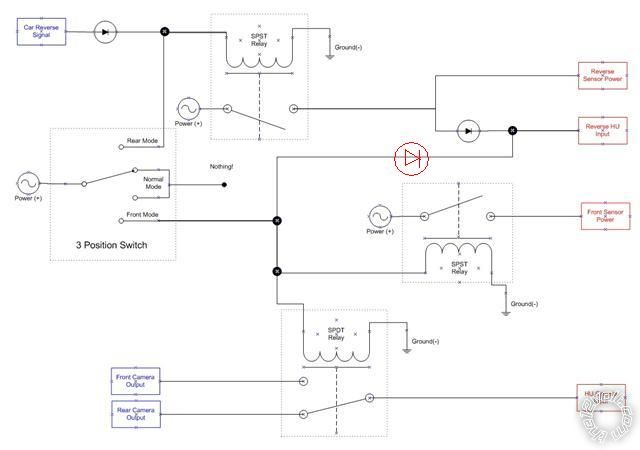
Hi, I'm new to electronics in general but I've installed a couple of headunits in my car, so I'm not completely clueless :) Just wanted to toss a circuit I'm planning to build out there so that people with proper electronics experience can have a look at it and let me know if I'm barking up the wrong tree, etc... Would appreciate any feedback, etc.. Have also included a diagram of the circuit.

4 different systems to be controlled by a single circuit, with 3 different modes(Normal, Rear Mode, Front Mode). 4 systems are:
1) Rear Parking sensors
2) Front parking sensors
3) Rear camera
4) Front camera
Inputs to circuit
a) Car reverse signal(triggered when car is put into reverse gear), 12v signal
b) Front camera output(signal coming from front camera), RCA composite
c) Rear Camera output(signal coming from rear camera), RCA composite
Outputs of circuit
d) Reversing sensors power(12v)
e) Front sensors power(12v)
f) Headunit Reverse signal(12v) - triggers headunit to display whatever is coming from camera input. If not on, headunit will NOT display camera input
g) Headunit camera input. RCA composite
Requirements:
Normal Mode
- Front camera OFF
- Front sensors OFF
- IF car is put into reverse,
- Rear camera ON
- Rear sensors ON
- All front(camera and sensors) OFF
Front Mode
- Front camera ON
- Front sensors ON
- IF car is put into reverse,
- Rear sensors ON
- Front Camera still ON
- Front Sensors still ON
Rear Mode
- All front(camera and sensors) OFF
- Rear camera ON
- Rear sensors ON
Assumptions:
1) Always have power supplied to cameras, and only switch the actual camera output via relay, so that display of image on HU is not dependant on startup time of camera
2) Where it says POWER on diagram, its switched power(ie. only powered when key is in ignition) so it does not drain the battery when car is not in use
3) When in normal mode, I want the default camera signal to be coming from Rear Camera. This is because in the headunit, there is an option to view the camera output WITHOUT the "Reverse HU Input" being triggered, and I want the default input to be coming from the rear camera
Notes on proposed circuit:
1) First diode connected to "Car Reverse Signal" is there so that power from the switch does not feed back into where I'm getting the "Car Reverse Signal" from, eg. car computer so as to lessen chances I fry the computer
2) 3 position switch in circuit shows 4 possible selections as I couldn't find a better shape in Visio! middle two selections are joined in diagram to show they are both connected to same thing...eg. nothing!
3) Even though the POWER shape has an AC wave in it, its meant to be DC 12v.
4) Inputs into circuit are colored blue, and outputs are colored red.
5) Not shown on diagram but I'll be putting quenching/suppression diodes across the coils of the relays
6) I was initially thinking of just using the video switching relay to just switch the video signal, but after a bit more research, I'm thinking I should switch the grounds from each signal as well. I'll be replacing that SPDT relay with a DPDT relay(or just add another SPDT relay to switch the ground).
 Printable version


 Hmmm - not too sure what to put....
Jack of all, Master of many?
I had my education interrupted by a 4 year injuneerink degree. (Started as electronics but got cheesed off & I majored in electrical.)
I had an interest in electronics etc and - because I didn't know any better - I often did the impossible. (Unfortunately that habit continued even after my degree.)
I've been involved in various fields & industries including automotive, military, legal, social - but now tend to be somewhat anti-social.
My last employment ended several years ago - a telecomms company - varied jobs from security, OH&S, systems management, power, product exits.
Since then I've probably spent most time trying to bring automotive & political) hobbyists into the new millennium.
