the12volt.com spacer
icon

09 f150, viper 5902 issues


Post ReplyPost New Topic
< Prev Topic Next Topic >
honcho 
Member - Posts: 4
Member spacespace
Joined: November 27, 2010
Location: New Brunswick, Canada
Posted: December 31, 2010 at 7:56 PM / IP Logged  
I wired viper 5902 into 09 f150 using pkfm, audio sensor, tilt sensor, field disturbance sensor, & back up battery. All sensors work and doors lock and unlock, system arms, unarms, however I have 2 issues.
1) when armed it shows that there is door open, wired to a negative trigger. If i switch to positive trigger, no door open issues. Every schematic I have seen shows 09 f150 super crew has negative door triggers. They are wired with diodes to each door.
2) I can't get into programming mode to change to auto trans, therefore, no remote start, however, I tried to remote start with key in ignition = no go. The three H3 - 12 volts constants are all wired together and connected to 1 constant 12 v supply.
Any assistance would be appreciated,
Honcho
kreg357 
Platinum - Posts: 7,827
Platinum spaceThis member has made a donation to the12volt.com. Click here for more info.spaceThis member has been recognized as an authority in Electrical Theory. Click here for more info.spaceThis member has been recognized as an authority in Mobile Security and Convenience. Click here for more info.spacespace
Joined: January 30, 2009
Location: Pennsylvania, United States
Posted: December 31, 2010 at 9:45 PM / IP Logged  

To get into programming, you can temporarily run the Vipers'  H1/8  (-) Door Trigger to chassis ground thru a switch.  That will fake out the Viper enough to get the option programming done.

How do the door triggers test with a DMM? 

Soldering is fun!
honcho 
Member - Posts: 4
Member spacespace
Joined: November 27, 2010
Location: New Brunswick, Canada
Posted: January 01, 2011 at 7:08 AM / IP Logged  

Hi and happy new years to everyone:

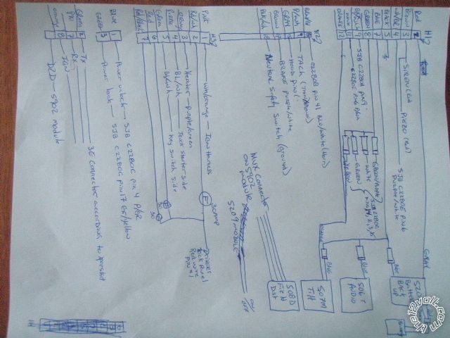
triggers are negative, added quick wiring sketch 

09 f150, viper 5902 issues -- posted image.

Honcho
honcho 
Member - Posts: 4
Member spacespace
Joined: November 27, 2010
Location: New Brunswick, Canada
Posted: January 01, 2011 at 7:17 AM / IP Logged  

just realised i forgot to add the red power from the 506 and 507, they are connected together and go to the gray of the 520 back up battery.and the black of the 506t  goes to H1/5 common ground

Honcho
honcho 
Member - Posts: 4
Member spacespace
Joined: November 27, 2010
Location: New Brunswick, Canada
Posted: January 01, 2011 at 10:49 AM / IP Logged  

good day again everyone i solved my issue... i had forgotten to put the doors back to H1/8 negative trigger. upon doing this the programming was accessible, after a few tries i got it to go into automatic mode, i also programmed the pkfm with the 2 coded keys, and the truck started up in remote mode.

in my previous post with the attachment, i forgot to show

1) the 506, 507, and 520 black connect together and go to the H1/5 which goes to the negative of the battery.

2) the 506,507, and 520 red connect together and go to a +12volt constant i brought in from battery.

also i removed the light flash H1/4 since the battery back up would drain to quickly with the lghts flashing, should the truck battery die.

now i'm left with aa few minor issues that i require assistance with

1) i get a "door opened" trigger when armed?

2) i get a "trunk open" trigger which i assume is because all my sensors connect to the blue (H1/7) wire which is the "instant trigger input/trunk pin status" as shown in the 5901 installation manual page 56. Is there away to change this to see independent sensors on the remote.

3)do i need to program menu 3 feature 2 option 4 "tachometer" or will the brain set this automatically, i did a test with ebrake on, key to on, foot over brake pedal, truck in drive, and i hit remote start on remote, the brain sent back a message to rem,ote that low tach voltage and the truck did not start so im assuming it set it to tachometer automatically, just looking for conformation.

4) for some reason i can not adjust the built in shock sensor sensitivity with the remote. i get to the F screen and to the shock sensitivity screen, but when i try to access i see contents for a second and it reverts back to the shock sensitivity screen. i assume you need the bitwriter to change this.

5)the Aux 1 - 4 and defroster buttons on remote, how do these work if at all, i was hoping to put my 506, 507, 508 sensors in here but havent figure out how, if possible, can anyone expalin these to me. thanks

6) on remote in sensor bypass screen, it shows warn away, shock sensors, optional sensors, and bypass all, but they all have a ! inside a yellow triangle, please explain.

7) on remote there is a runtime reset, which i can not get to operate, explainaition required.

Honcho

Sorry, you can NOT post a reply.
This topic is closed.

  Printable version Printable version Post ReplyPost New Topic
You cannot post new topics in this forum
You cannot reply to topics in this forum
You cannot delete your posts in this forum
You cannot edit your posts in this forum
You cannot create polls in this forum
You cannot vote in polls in this forum

  •  
Search the12volt.com
Follow the12volt.com Follow the12volt.com on Facebook
Sunday, May 18, 2025 • Copyright © 1999-2025 the12volt.com, All Rights Reserved Privacy Policy & Use of Cookies
Disclaimer: *All information on this site ( the12volt.com ) is provided "as is" without any warranty of any kind, either expressed or implied, including but not limited to fitness for a particular use. Any user assumes the entire risk as to the accuracy and use of this information. Please verify all wire colors and diagrams before applying any information.

Secured by Sectigo
the12volt.com spacer
Support the12volt.com
Top
the12volt.com spacer