the12volt.com spacer
icon

02 venture, radiostar gen door locks


Post ReplyPost New Topic
< Prev Topic Next Topic >
chilliwillee 
Member - Posts: 4
Member spacespace
Joined: April 06, 2013
Location: Nova Scotia, Canada
Posted: April 06, 2013 at 12:19 PM / IP Logged  
I have installed a Radiostar Generation 2-way remote starter with alarm and door locks. I have the starter working fine but don't understand what exactly has to be done to install the locks.
It has a harness which contains wires for the relays, a power wire and a ground. It also has a blue wire listed as "second unlock (passenger unlock) output (-) 200mA" which allows for multiplex lock control.
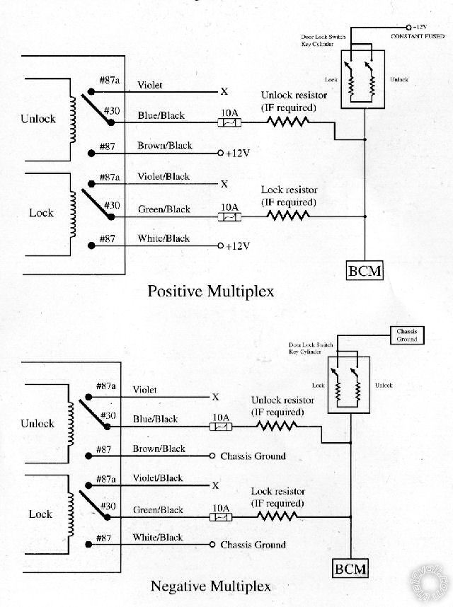
There are diagrams in the book, but no real explaination of what the diagrams are showing (factory wiring or hook up wiring), and it doesn't show the blue wire so I am not sure where this wire hooks up and whether I simply tap into the relay output wires at the BCM to hook up the remote control relay wires, or if it is just triggers that are required to allow the BCM to handle the locks. If it is triggers, then which wires from the remote and where?
From Remote:
Violet: Unlock 87a normally closed
Blue/Black: unlock 30 common (output)
BROWN / Black: unlock 87 normally open (Input)
Violet/Black: lock 87a normally closed
GREEN/ Black: lock 30 common (output)
WHITE/ Black: Lock 87 normally open (input)
(10, 87 and 87a being standard positions on the relays)
Blue: second unlock (passenger unlock) output (-) 200mA. This system is equipped with a dedicated passenger unlock output allowing 2-stage door unlock operation. When connected this wire, disarming will unlock only the driver's door. Pressing disarm again will unlock all doors.
02 venture, radiostar gen door locks -- posted image.
I am probably making this more complicated then it is which is stopping the answer from showing itself. LOL
Leland
howie ll 
Pot Metal - Posts: 16,466
Pot Metal spacespace
Joined: January 09, 2007
Location: United Kingdom
Posted: April 06, 2013 at 2:03 PM / IP Logged  
Nothing like the above and forget "multiplex", the blue wire is for priority unlock i.e. driver door first then the others. Here's how.:-
venture.bmp
chilliwillee 
Member - Posts: 4
Member spacespace
Joined: April 06, 2013
Location: Nova Scotia, Canada
Posted: April 06, 2013 at 3:30 PM / IP Logged  
As I read the diagram, the BLACK/ white and PURPLE / black are in the 6-pin outputs harness and the GREEN/ black is the one in the 8-pin inputs/outputs harness. The violet, BROWN / black and blue/black are in the 10-pin primary harness. The BROWN / black is currently an un-fused input and will become a fused constant 12V input.
There are 2 tans coming from the white plug, but I assume testing continuity with the wires in the kick panel will show me which one is driver's door.
howie ll 
Pot Metal - Posts: 16,466
Pot Metal spacespace
Joined: January 09, 2007
Location: United Kingdom
Posted: April 06, 2013 at 4:33 PM / IP Logged  
Er no I just used the wires listed by yourself in the diagrams you posted, the blue being the above mentioned second lock output.
chilliwillee 
Member - Posts: 4
Member spacespace
Joined: April 06, 2013
Location: Nova Scotia, Canada
Posted: April 06, 2013 at 4:54 PM / IP Logged  
Ok, that is why I wanted to verify. You changed Violet/blck to PURPLE / black and WHITE/ black to BLACK/ white, which match wires in a different harness. After looking at both diagrams it makes sense now. I was taking the Radiostar diagrams as showing connections to external relays when in fact they are showing the internals of their system. As I said, I was making things too complicated to see the answer.
howie ll 
Pot Metal - Posts: 16,466
Pot Metal spacespace
Joined: January 09, 2007
Location: United Kingdom
Posted: April 06, 2013 at 5:01 PM / IP Logged  
Yes I was going to make a comment about these things are nearly always "over analysed" by amateurs but I take the thought back, humble apologies because you understood.
chilliwillee 
Member - Posts: 4
Member spacespace
Joined: April 06, 2013
Location: Nova Scotia, Canada
Posted: April 06, 2013 at 6:01 PM / IP Logged  
Thanks, I think. Lol
It all works. I am not sure I would have come up with splitting the tan wire on my own, at least not for a while.
At first it wouldn't lock, just set off the chime; then I noticed the side door wasn't closed tight. Once that was closed, everything went perfecrly.
Thanks for all the help, saved a day of head scratching and lots of swearing. ;-)
Leland
howie ll 
Pot Metal - Posts: 16,466
Pot Metal spacespace
Joined: January 09, 2007
Location: United Kingdom
Posted: April 06, 2013 at 11:10 PM / IP Logged  
Good for you 02 venture, radiostar gen door locks -- posted image.
I've only 2 questions;
a) WTH is a Venture?
b) wth is a Radiostar?
PS Don't worry I really don't care.

Sorry, you can NOT post a reply.
This topic is closed.

  Printable version Printable version Post ReplyPost New Topic
You cannot post new topics in this forum
You cannot reply to topics in this forum
You cannot delete your posts in this forum
You cannot edit your posts in this forum
You cannot create polls in this forum
You cannot vote in polls in this forum

  •  
Search the12volt.com
Follow the12volt.com Follow the12volt.com on Facebook
Sunday, July 13, 2025 • Copyright © 1999-2025 the12volt.com, All Rights Reserved Privacy Policy & Use of Cookies
Disclaimer: *All information on this site ( the12volt.com ) is provided "as is" without any warranty of any kind, either expressed or implied, including but not limited to fitness for a particular use. Any user assumes the entire risk as to the accuracy and use of this information. Please verify all wire colors and diagrams before applying any information.

Secured by Sectigo
the12volt.com spacer
Support the12volt.com
Top
the12volt.com spacer