the12volt.com spacer
icon

powerfist brand wireless remote kit


Post ReplyPost New Topic
< Prev Topic Next Topic >
quintenrc 
Member - Posts: 4
Member spacespace
Joined: May 19, 2013
Location: British Columbia, Canada
Posted: May 19, 2013 at 9:09 PM / IP Logged  
I have a 1993 Dodge Grand Caravan ES, and I picked up this kit @ Princess Auto, PowerFist part #8003441. (I was feeling impulsive and it was on sale.) All I want from it is Remote Keyless Entry and Trunk Release. Through testing I have surmised that the door lock system is a 3 wire positive, and trunk release is 1 wire positive. My question is: Where would be the best place to get fused 12V+ from for terminals 85,87 (lock relay) and 86,87 (unlock relay)and does it need to be constant? I am going by the 3 wire positive lock diagram I found on this site, which seems to apply as this PowerFist units' internal relays are only 15A and it didn't work when I hooked it up without the extra relays. (I can hear the internal click of the units' relay, but there's no actual locky-unlocky) This is my first install of this type and I just want to be sure before I go balls-deep with it. Any additional tips or input gladly welcomed.
free admission, pay at the door--pull up a chair, and sit on the floor.
howie ll 
Pot Metal - Posts: 16,466
Pot Metal spacespace
Joined: January 09, 2007
Location: United Kingdom
Posted: May 19, 2013 at 10:18 PM / IP Logged  
Don't know what you are doing wrong but but 15 amp internal relays would be more than powerful enough, you're only triggering existing relays. (120 mAmps).
You're looking for a POS output on your lock wires to trigger the existing relays.
This is a typical pos trunk release set-up:- C86_trunk_release.bmp
The fuse box input and yes it has to be a constant.
And no you mean 86 and 87 NOT 85 and 87.
howie ll 
Pot Metal - Posts: 16,466
Pot Metal spacespace
Joined: January 09, 2007
Location: United Kingdom
Posted: May 19, 2013 at 10:21 PM / IP Logged  
This should be your lock outputs on your unit, never heard of it which should tell you something.
30 = Common
87a = NC
87 = NO
86 = coil +
85 = coil -
Since 85 and 86 are internal ASSUMING internal relays, your unit should have 6 lock wires.
quintenrc 
Member - Posts: 4
Member spacespace
Joined: May 19, 2013
Location: British Columbia, Canada
Posted: May 19, 2013 at 11:28 PM / IP Logged  
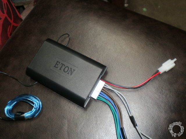
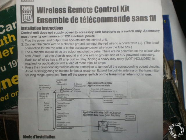
Thanks for the prompt reply! This is the unit and the instructions that came with it. When I tested it, I had used one wire from Grey and one wire from Brown (Channels 1 and 2) hooked to the lock/unlock wires coming out of the drivers side power lock switch. The other wire from each channel was grounded. Am I just hooking in at the wrong place in the circuit? [IMG]uploads/p5190487.jpg[/IMG][IMG]uploads/p5190489.jpg[/IMG]
free admission, pay at the door--pull up a chair, and sit on the floor.
quintenrc 
Member - Posts: 4
Member spacespace
Joined: May 19, 2013
Location: British Columbia, Canada
Posted: May 19, 2013 at 11:30 PM / IP Logged  
ffs...I don't think my upload worked.. I will try to get those images on here
free admission, pay at the door--pull up a chair, and sit on the floor.
quintenrc 
Member - Posts: 4
Member spacespace
Joined: May 19, 2013
Location: British Columbia, Canada
Posted: May 19, 2013 at 11:41 PM / IP Logged  
powerfist brand wireless remote kit -- posted image.
free admission, pay at the door--pull up a chair, and sit on the floor.

Sorry, you can NOT post a reply.
This topic is closed.

  Printable version Printable version Post ReplyPost New Topic
You cannot post new topics in this forum
You cannot reply to topics in this forum
You cannot delete your posts in this forum
You cannot edit your posts in this forum
You cannot create polls in this forum
You cannot vote in polls in this forum

  •  
Search the12volt.com
Follow the12volt.com Follow the12volt.com on Facebook
Monday, July 7, 2025 • Copyright © 1999-2025 the12volt.com, All Rights Reserved Privacy Policy & Use of Cookies
Disclaimer: *All information on this site ( the12volt.com ) is provided "as is" without any warranty of any kind, either expressed or implied, including but not limited to fitness for a particular use. Any user assumes the entire risk as to the accuracy and use of this information. Please verify all wire colors and diagrams before applying any information.

Secured by Sectigo
the12volt.com spacer
Support the12volt.com
Top
the12volt.com spacer