


starter kill


Posted: October 23, 2014 at 10:51 AM / IP Logged

Posted: October 23, 2014 at 12:13 PM / IP Logged
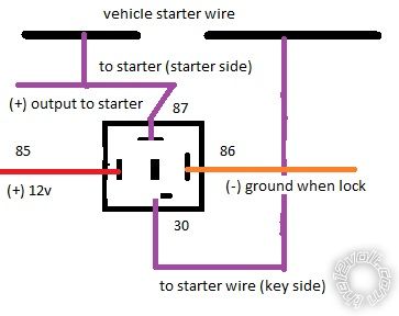
 Using this diagram - you should have continuity between 30 and 87a (normally closed) when the relay is not energized. When it is energized you will have continuity between 30 and 87.
When the unit arms ground is sent to the relay coil pin 85. At this point the coil is not energized, but If you put the key in and try to crank, ignition voltage would be applied to the other side of the relay energizing the coil and opening the starter circuit.
Be sure to use Ignition (+)12v to the relay coil that way you wont have a constant 12 volts going to the relay potentially draining the battery.
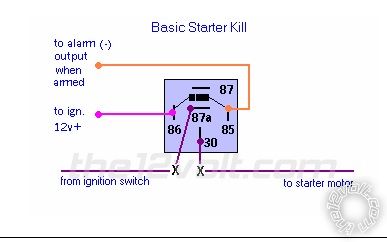
Using this diagram - you should have continuity between 30 and 87a (normally closed) when the relay is not energized. When it is energized you will have continuity between 30 and 87.
When the unit arms ground is sent to the relay coil pin 85. At this point the coil is not energized, but If you put the key in and try to crank, ignition voltage would be applied to the other side of the relay energizing the coil and opening the starter circuit.
Be sure to use Ignition (+)12v to the relay coil that way you wont have a constant 12 volts going to the relay potentially draining the battery.Posted: October 23, 2014 at 1:07 PM / IP Logged
Sorry, you can NOT post a reply.
This topic is closed.
 Printable version
| You cannot post new topics in this forum You cannot reply to topics in this forum You cannot delete your posts in this forum You cannot edit your posts in this forum You cannot create polls in this forum You cannot vote in polls in this forum |

| Search the12volt.com |
Follow the12volt.com 
Sunday, April 5, 2026 • Copyright © 1999-2026 the12volt.com, All Rights Reserved • Privacy Policy & Use of Cookies

Sunday, April 5, 2026 • Copyright © 1999-2026 the12volt.com, All Rights Reserved • Privacy Policy & Use of Cookies
Disclaimer:
*All information on this site ( the12volt.com ) is provided "as is" without any warranty of any kind, either expressed or implied, including but not limited to fitness for a particular use. Any user assumes the entire risk as to the accuracy and use of this information. Please
verify all wire colors and diagrams before applying any information.
