the12volt.com spacer
icon

Help on an Install


Post ReplyPost New Topic
< Prev Topic Next Topic >
indecent_x 
Member - Posts: 2
Member spacespace
Joined: November 16, 2004
Location: United States
Posted: November 16, 2004 at 6:03 PM / IP Logged  

Hi, I recently pruchased an Phoenix Digital PD-175 alarm sys.  and I recieved it and would like to install it myself.  I check around to see how much an professional install will cost me and the lowest I found it was $300 so needless to say --here I am.  What I basically need is all the information you guys feel is neccessary since I have limited experience installing alarms in particular (I have a lot of experience with other electronics, stereos and computer but not alarms).  If somebody has an wiring diagram for my car that would also be very helpfull. 

Now the important info:

Car: 2002 Dodge Neon Base Model

  • Manual Transmission
  • No Power windows or locks (I plan on installing power doors in a couple of days)
  • No Key Chip

Alarm: Phoenix Digital PD-175

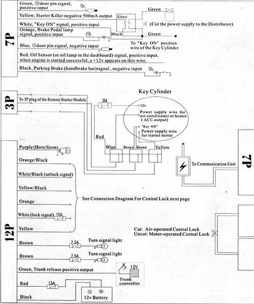
Here is the image of the wiring diagram for the alarm:

Help on an Install -- posted image.

auex 
Platinum - Posts: 5,041
Platinum spaceThis member has made a donation to the12volt.com. Click here for more info.spacespace
Joined: December 23, 2002
Location: Arizona, United States
Posted: November 16, 2004 at 7:04 PM / IP Logged  
Well there will be one wire that no diagram I have seen has. So go find the oil pressure sender wire before asking for the rest of the diagram. If you can't find it then get a different alarm.
Certified Security Specialist
Always check info with a digital multimeter.
I promise to be good.
Tell Darwin I sent you.
I've been sick lately, sorry I won't be on much.
Velocity Motors 
Moderator - Posts: 12,488
Moderator spaceThis member has made a donation to the12volt.com. Click here for more info.spaceThis member has been recognized as an authority in Electrical Theory. Click here for more info.spaceThis member has been recognized as an authority in Fabrication. Click here for more info.spaceThis member has been recognized as an authority in Mobile Audio and Video. Click here for more info.spaceThis member has been recognized as an authority in Mobile Security and Convenience. Click here for more info.spacespace
Joined: March 08, 2002
Location: Manitoba, Canada
Posted: November 16, 2004 at 8:14 PM / IP Logged  
I think that RED wire is for the alternator sense wire, auex.
Jeff
Velocity Custom Home Theater
Mobile Audio/Video Specialist
Morden, Manitoba CANADA
jrilla 
Gold - Posts: 1,498
Gold spaceThis member has made a donation to the12volt.com. Click here for more info.spacespace
Joined: November 19, 2002
Location: North Dakota, United States
Posted: November 16, 2004 at 10:56 PM / IP Logged  
Yeah Jeff is right, that red wire needs to be hooked up to 12v+ constant to monitor the voltage. I had a guy who tried to install one of these and it didn't work so I helped him find the oil sensor wire and that didn't even work, so I decided to try hooking up to 12v+ constant and then it worked.
I don't think that unit is designed for manual transmission vehicles though. Don't install the remote starter features if it is not. You can buy a peripheral Neutral safety switch if you are so determined to install the starter feature. I don't have the link to where you can buy one, but they are out there.
J Rilla
Owner/Installer
indecent_x 
Member - Posts: 2
Member spacespace
Joined: November 16, 2004
Location: United States
Posted: November 17, 2004 at 5:26 AM / IP Logged  

I think that I won't be installing the Remote Starter feature.  It just seems to much trobuble and I can't image that I will find it that usefull anyway.

In any case it does seem that this sys. was designed for automatic trans. but I do have a couple more questions.

The RED wire from the 7 pin connector as it says needs to be hooked up to the 12V+ which is energized after the eninge has been started.  But the oil lamp goes off when the engine starts therefore de-enegizing the 12V+ hhhmm.  It does seem that connecting it to the alternator wire makes a lot more sense.

Also it says that the ORANGE from the 7 pin connector goes to the BRAKE PEDAL LIGHT???  I would assume that it was meant for cars equipt. with automatic trans where you need to depress the brake pedal to start the car.  Now since I have no such thing, would it be possible to hook it up to one of the constant 12V+ power inputs or even to a switch or one of the lamps that goes on when put the key in the ingition. 

Suggestions are greatly appreaciated.

jrilla 
Gold - Posts: 1,498
Gold spaceThis member has made a donation to the12volt.com. Click here for more info.spacespace
Joined: November 19, 2002
Location: North Dakota, United States
Posted: November 17, 2004 at 11:21 AM / IP Logged  
There is a switch above the brake pedal that triggers your brake lights when you press on the brake to let drivers behind you know that you are braking. One of the wires reads 12v+ when the brake is depressed and that is the wire you need to grab.
The red wire needs 12v+ constant (found in the ignition harness where you also will connect the fused red wire in the 12pin harness) so the unit can monitor the voltage and look for an increase when the alternator kicks on.
J Rilla
Owner/Installer

Sorry, you can NOT post a reply.
This topic is closed.

  Printable version Printable version Post ReplyPost New Topic
You cannot post new topics in this forum
You cannot reply to topics in this forum
You cannot delete your posts in this forum
You cannot edit your posts in this forum
You cannot create polls in this forum
You cannot vote in polls in this forum

  •  
Search the12volt.com
Follow the12volt.com Follow the12volt.com on Facebook
Tuesday, July 15, 2025 • Copyright © 1999-2025 the12volt.com, All Rights Reserved Privacy Policy & Use of Cookies
Disclaimer: *All information on this site ( the12volt.com ) is provided "as is" without any warranty of any kind, either expressed or implied, including but not limited to fitness for a particular use. Any user assumes the entire risk as to the accuracy and use of this information. Please verify all wire colors and diagrams before applying any information.

Secured by Sectigo
the12volt.com spacer
Support the12volt.com
Top
the12volt.com spacer