


remote start in 96 Civic
Home /
the12volt's Install Bay /
Car Security and Convenience / remote start in 96 Civic ( Topic Closed)


Posted: May 18, 2006 at 10:35 AM / IP Logged
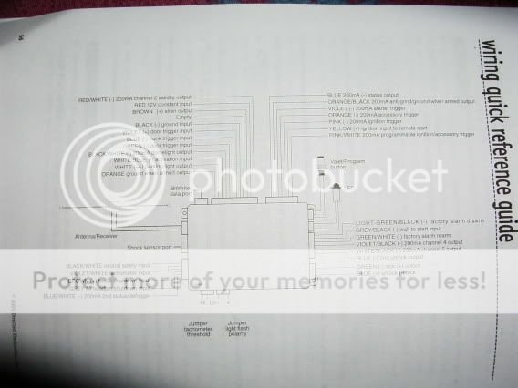 Issues with picture 1:
1) Involves top second to left harness (main harness).not sure where the "WHITE/ blue (-) activation input" wire connects to. I suspect that it connects to the "blue (-) status output" wire on the Relay Satellite (pic two).
2) involves bottom left harness. not sure what is needed to be done(bypass) with the "BLACK/ white neutral safety input" wire and the "grey (-) hoodpin shutdown input" and the "blue/white (-) 200mA 2nd status/defogger" wire.
Picture 2 - Relay Satellite
Issues with picture 1:
1) Involves top second to left harness (main harness).not sure where the "WHITE/ blue (-) activation input" wire connects to. I suspect that it connects to the "blue (-) status output" wire on the Relay Satellite (pic two).
2) involves bottom left harness. not sure what is needed to be done(bypass) with the "BLACK/ white neutral safety input" wire and the "grey (-) hoodpin shutdown input" and the "blue/white (-) 200mA 2nd status/defogger" wire.
Picture 2 - Relay Satellite
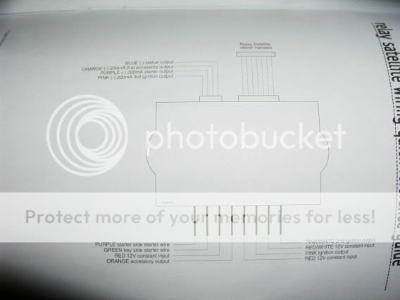 Issues with picture 2 (involves harness on the top left of module):
1) same as issue 1 for picture 1. I think the "blue (-) satus output" goes to the "WHITE/ blue (-) activation input" in picture one.
2) not sure if the "purple (-) 200mA starter output" wire should be connected to the "Purple starter side starter wire" (bottom harness in pic).
3) I'm sure that the Orange and Pink wire in this harness can be omitted. Can anyone confirm this?
Issues with picture 2 (involves harness on the top left of module):
1) same as issue 1 for picture 1. I think the "blue (-) satus output" goes to the "WHITE/ blue (-) activation input" in picture one.
2) not sure if the "purple (-) 200mA starter output" wire should be connected to the "Purple starter side starter wire" (bottom harness in pic).
3) I'm sure that the Orange and Pink wire in this harness can be omitted. Can anyone confirm this?


Posted: May 18, 2006 at 12:12 PM / IP Logged
Sorry, you can NOT post a reply.
This topic is closed.
 Printable version
| You cannot post new topics in this forum You cannot reply to topics in this forum You cannot delete your posts in this forum You cannot edit your posts in this forum You cannot create polls in this forum You cannot vote in polls in this forum |

| Search the12volt.com |
Follow the12volt.com 
Wednesday, March 25, 2026 • Copyright © 1999-2026 the12volt.com, All Rights Reserved • Privacy Policy & Use of Cookies

Wednesday, March 25, 2026 • Copyright © 1999-2026 the12volt.com, All Rights Reserved • Privacy Policy & Use of Cookies
Disclaimer:
*All information on this site ( the12volt.com ) is provided "as is" without any warranty of any kind, either expressed or implied, including but not limited to fitness for a particular use. Any user assumes the entire risk as to the accuracy and use of this information. Please
verify all wire colors and diagrams before applying any information.
