the12volt.com spacer
icon

lighting relay


Post ReplyPost New Topic
< Prev Topic Next Topic >
fish2live 
Member - Posts: 10
Member spacespace
Joined: June 30, 2008
Location: Washington, United States
Posted: November 20, 2008 at 12:42 PM / IP Logged  

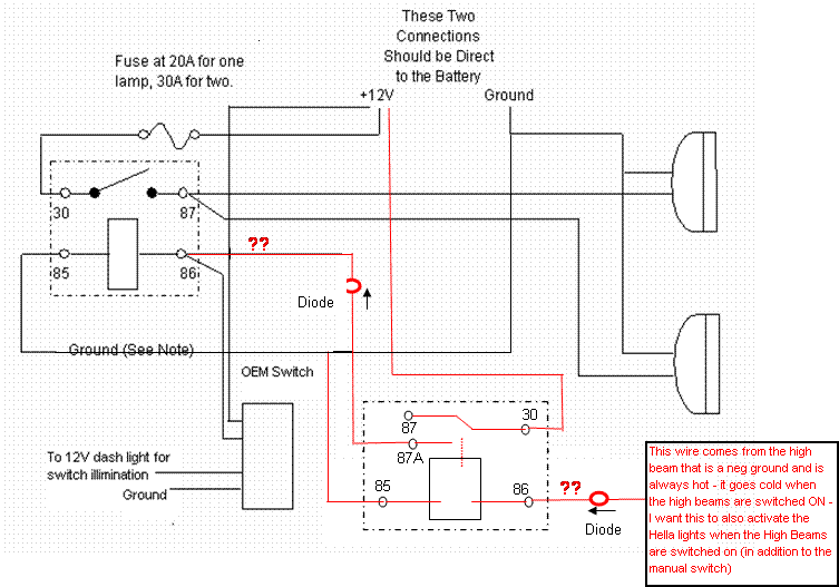
My objective - to have aux Hella Rally lights that will work with an OEM switch on the dash via a relay - this is working great today.  I want to add (in red in the diagram) the ability for those same lights to ALSO switch ON when the High Beams are activated.  The issue I'm having is that the High Beams are Neg ground and are hot when off, and go cold when I turn them on. I posted a while ago and had the following advice: 

~~~~~~~~~~~~~~~~~~~~~~~~~~~~~~~~~~~~~~~~~~~~~~~~~~~~~~~~~~~

lighting relay -- posted image.

Ground terminal 85     The 12 volt switched wire that controls the relay to terminal 86.   Terminal 30 goes to the battery via a fuse mounted at the battery.  Terminal 87A will supply voltage to the light.

The only problem with this setup is the coil of the relay is energized all of the time.  It WILL run a battery down.

~~~~~~~~~~~~~~~~~~~~~~~~~~~~~~~~~~~~~~~~~~~~~~~~~~~~~~~~~~~~~~~~~~~~

I'm a little confused (sorry, I'm a wiring idiot!!)....  would the following diagram work?  Do I need BOTH diodes (or any diodes at all?)  Items in black are installed and working - red is new and open to your suggestions.. 

lighting relay -- posted image.

rookie
fish2live 
Member - Posts: 10
Member spacespace
Joined: June 30, 2008
Location: Washington, United States
Posted: November 20, 2008 at 1:27 PM / IP Logged  
if you click on the pic the lines will clear up a bit with better resolution...  at least that's what happens on my computer...
rookie
fish2live 
Member - Posts: 10
Member spacespace
Joined: June 30, 2008
Location: Washington, United States
Posted: November 22, 2008 at 9:25 PM / IP Logged  
just wondering if nobody understands this or maybe my question just doesn't make sense??? i figured I'd have a response by now.....lighting relay -- posted image.
rookie
fish2live 
Member - Posts: 10
Member spacespace
Joined: June 30, 2008
Location: Washington, United States
Posted: November 25, 2008 at 12:36 PM / IP Logged  

Did I say something wrong?  I'm used to at least SOME type of response on other boards.....  to not have a single one is rather strange.

rookie
dualsport 
Silver - Posts: 983
Silver spacespace
Joined: September 27, 2005
Location: United States
Posted: November 26, 2008 at 9:15 PM / IP Logged  
Sorry I got to the party late, but I just stopped in to browse around a bit- mebbe everyone's prepping for their turkey dinner- lighting relay -- posted image.
One thing you could do is to connect an ignition switched line to terminal 85 of your new relay with a diode in series (with the cathode towards the relay). If you connected it to ground the way you show in the diagram, the relay would always be on until you turn your high beams on, not what you want.
Connecting it to a switched ignition line, the relay only energizes when your ignition is on and the high beams switched on. When the ignition is off (and I assume you won't want to turn on your driving lights then), the diode will block any current from backflowing from your high beams.
The rest of the circuit you could use as you drew up (you may want to add a diode between your OEM switch and the relay terminal 86 if your car doesn't like any backfeed from the other relay.) If it doesn't care, you can wire it in directly as you show in your diagram.
Or you could use your added relay to power the aux lights directly, though that means you'll need heavy duty wiring instead of just some thin control wires. I'd just use the relay to control the first one like you did, that'd be the best way.
fish2live 
Member - Posts: 10
Member spacespace
Joined: June 30, 2008
Location: Washington, United States
Posted: December 03, 2008 at 1:55 AM / IP Logged  
Hi there dualsport (by the way, I have a KTM EXC400 that I Dualsport!!) - anyway - THANK YOU VERY MUCH for the response - I don't think I quite get what to do for your first suggestion. The line going into 85 on the new relay is a ground line, but you're saying make it a 12v positive power line that is only switched on with the ignition..? Right? I think I get that part, but wouldn't that mean that the relay has 2 power lines in - one at 85 and one at 86 - both energized when the ignition is on? Sorry again - I am a wiring idiot!!
rookie
dualsport 
Silver - Posts: 983
Silver spacespace
Joined: September 27, 2005
Location: United States
Posted: December 03, 2008 at 1:07 PM / IP Logged  

If I read your description correctly, your high beam line (the one you were going to use to control the relay) is normally sitting at 12V when the high beams are off, and goes to ground when you turn on the high beams.

If that's correct, my suggestion was to use that as the ground side of the relay coil, so that the relay is only turned on when you have the high beams on (so the line is grounded), and the ignition is on.

The 12V for the relay is coming from the switched ignition line, and the ground is from your high beam line. You'll have to flip the direction of the diode that you show in the diagram so that the current flows out of the relay coil towards the high beam control line, if you hook it up on the high beam side.

Maybe I should point out that a relay works when there's a difference in voltage between the relay coil input terminals. If you apply 12V to both sides of the coil, the net voltage is zero, same as if both sides had zero volts on them. Zero volts means the relay is not turned on.
In your case, the relay will only see 12V when you turn on the high beams, which brings that side to ground, while the ign switched 12V is supplying the power.   
If your ignition is off, and you have the high beams off, then that would put 12V across the coil in the reverse direction, which would also turn it on, which you don't want happening. So that's why you would have to add a diode, to block the current flowing in that direction.
KLR650 :-)
fish2live 
Member - Posts: 10
Member spacespace
Joined: June 30, 2008
Location: Washington, United States
Posted: December 13, 2008 at 11:41 AM / IP Logged  

alright - it worked perfect!!

THANK YOU!!!

I have another question soon as well, stay tuned

rookie
dualsport 
Silver - Posts: 983
Silver spacespace
Joined: September 27, 2005
Location: United States
Posted: December 14, 2008 at 8:17 AM / IP Logged  
Good to hear it worked out- nice KTM!
fish2live 
Member - Posts: 10
Member spacespace
Joined: June 30, 2008
Location: Washington, United States
Posted: December 14, 2008 at 3:09 PM / IP Logged  

Thanks, it's a 453 actually (big bore kit) with a Yoshi pipe and Rekluse auto-clutch.

I'll post my other question in another thread!!

rookie
Page of 2

  Printable version Printable version Post ReplyPost New Topic
You cannot post new topics in this forum
You cannot reply to topics in this forum
You cannot delete your posts in this forum
You cannot edit your posts in this forum
You cannot create polls in this forum
You cannot vote in polls in this forum

  •  
Search the12volt.com
Follow the12volt.com Follow the12volt.com on Facebook
Thursday, October 31, 2024 • Copyright © 1999-2024 the12volt.com, All Rights Reserved Privacy Policy & Use of Cookies
Disclaimer: *All information on this site ( the12volt.com ) is provided "as is" without any warranty of any kind, either expressed or implied, including but not limited to fitness for a particular use. Any user assumes the entire risk as to the accuracy and use of this information. Please verify all wire colors and diagrams before applying any information.

Secured by Sectigo
the12volt.com spacer
Support the12volt.com
Top
the12volt.com spacer