the12volt.com spacer
icon

wiring relay latch/switch


Post ReplyPost New Topic
< Prev Topic Next Topic >
nick88 
Member - Posts: 9
Member spacespace
Joined: July 08, 2007
Location: Australia
Posted: July 08, 2007 at 4:16 AM / IP Logged  
Hey guys, got a bit of a problem and after some help, now i have a bit of electronic knowledge but not heaps...anyway, today i had a go at making a latch circuit with two relays so that i can still have my radio on with the ign key off but when i open the drivers door, it switches off...exactly like the VZ commodores do.
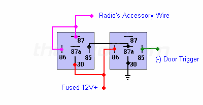
I found a tut thing on a website ( Special Applications with SPDT Relays) and it does work, just the opposite way to what i need, lol....so when the door is closed the radio goes off but with the door open and i turn the key to off the radio stays on! wiring relay latch/switch -- posted image.
I had a bit of a muck around with the wiring and adding another relay to the circuit to try and make the circuit open when door is open and circuit closed when door is closed, but as it is with just the two relays is the other way(circuit open when door closed circuit closed when door open)
Can anyone please help me with this and tell me how to re-wire it or wire in the 3rd relay to make it work?
Thankz
Nick
hotwaterwizard 
Silver - Posts: 1,350
Silver spacespace
Joined: December 11, 2003
Location: California, United States
Posted: July 09, 2007 at 11:12 PM / IP Logged  

Okay Show me what you did?

Is the door switch used for anything else?

Is this door switch open when the door is closed or closed when the door is closed?

John DeRosa (Hotwaterwizard)
Stockton California
When in doubt, try it out !
hotwaterwizard 
Silver - Posts: 1,350
Silver spacespace
Joined: December 11, 2003
Location: California, United States
Posted: July 09, 2007 at 11:28 PM / IP Logged  

Exactly how would you like it to work?

1) Turn the key on and the relay latches

2) Turn the key off and nothing happens

3) Open the door and off it goes.

4) No power drawn from the circuit when in the off position.

John DeRosa (Hotwaterwizard)
Stockton California
When in doubt, try it out !
hotwaterwizard 
Silver - Posts: 1,350
Silver spacespace
Joined: December 11, 2003
Location: California, United States
Posted: July 09, 2007 at 11:38 PM / IP Logged  

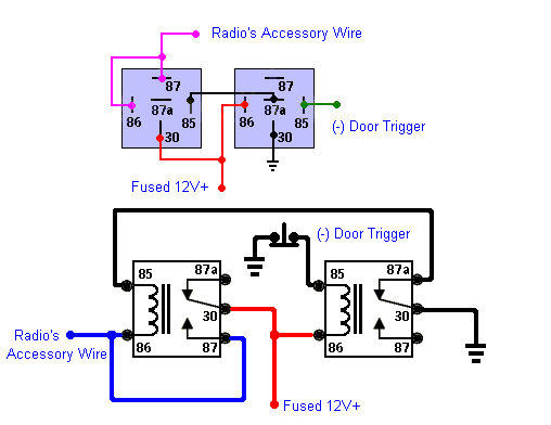
What is wrong with the diagram you linked to?

wiring relay latch/switch -- posted image.

John DeRosa (Hotwaterwizard)
Stockton California
When in doubt, try it out !
hotwaterwizard 
Silver - Posts: 1,350
Silver spacespace
Joined: December 11, 2003
Location: California, United States
Posted: July 10, 2007 at 12:01 AM / IP Logged  

Something is wrong with this circuit.

wiring relay latch/switch -- posted image.

John DeRosa (Hotwaterwizard)
Stockton California
When in doubt, try it out !
nick88 
Member - Posts: 9
Member spacespace
Joined: July 08, 2007
Location: Australia
Posted: July 10, 2007 at 2:23 AM / IP Logged  

Hey,  yes the door switch is used for the interior lighting,  the door switch grounds when the door is open to turn the lights on and is disconnected from ground when the door is closed to turn the lights off...

How i want it to work is when i turn the key to off(with the door closed) is stays on but as soon as i open the door it turns it off,  so kind of reversing the switch but only for the door trigger wire not the interior lighting wire

and i cant see whats wrong with the circuit(not that i know what im looking for....lol)

Thankz

Nick

hotwaterwizard 
Silver - Posts: 1,350
Silver spacespace
Joined: December 11, 2003
Location: California, United States
Posted: July 10, 2007 at 9:46 PM / IP Logged  

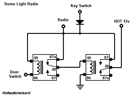
Nick, I drew this one for you.

The first relay is inactive until the second one is latched. The key switch signal latches it on. The diode stops the voltage from going back into the key switch circuit. Almost any Diode will work.

When the Relay latches it gets power from the hot wire. Voltage goes thru the first relay 87a to 30 then to the coil of the second relay. When the key is off the first relay still has a hot on pin 85 but nothing happens because the door switch provides the ground for the other side of the coil.

When the door is opened it will give relay 1 a ground and unlatch the second relay and drop the power to it's self as well. No power goes to it untill the key is back on.

wiring relay latch/switch -- posted image.

John DeRosa (Hotwaterwizard)
Stockton California
When in doubt, try it out !
nick88 
Member - Posts: 9
Member spacespace
Joined: July 08, 2007
Location: Australia
Posted: July 11, 2007 at 3:38 AM / IP Logged  

Awsome,  thankz for your help hotwaterwizard...

so that new diag u drew me is how i should set it up yea? i dont have to do anything with the door switch to reverse the switch?

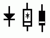
Also,,  is the diode the lil triangle thingy with a line? what diode should i get? i do really need it?

Nick

nick88 
Member - Posts: 9
Member spacespace
Joined: July 08, 2007
Location: Australia
Posted: July 11, 2007 at 8:33 AM / IP Logged  

ok, just tried it then...and didnt work:(....although i didnt put the diode thingy in, does that matter? or should it still work?

it was doin the exact same thing as before, turns off with the door closed but stays on with the door open....damn thing!

Nick

hotwaterwizard 
Silver - Posts: 1,350
Silver spacespace
Joined: December 11, 2003
Location: California, United States
Posted: July 11, 2007 at 8:38 AM / IP Logged  

You can try it without the Diode but I would put one in  myself.

wiring relay latch/switch -- posted image.

John DeRosa (Hotwaterwizard)
Stockton California
When in doubt, try it out !
Page of 3

  Printable version Printable version Post ReplyPost New Topic
You cannot post new topics in this forum
You cannot reply to topics in this forum
You cannot delete your posts in this forum
You cannot edit your posts in this forum
You cannot create polls in this forum
You cannot vote in polls in this forum

  •  
Search the12volt.com
Follow the12volt.com Follow the12volt.com on Facebook
Thursday, May 8, 2025 • Copyright © 1999-2025 the12volt.com, All Rights Reserved Privacy Policy & Use of Cookies
Disclaimer: *All information on this site ( the12volt.com ) is provided "as is" without any warranty of any kind, either expressed or implied, including but not limited to fitness for a particular use. Any user assumes the entire risk as to the accuracy and use of this information. Please verify all wire colors and diagrams before applying any information.

Secured by Sectigo
the12volt.com spacer
Support the12volt.com
Top
the12volt.com spacer